Page 1222 of 2189

tt
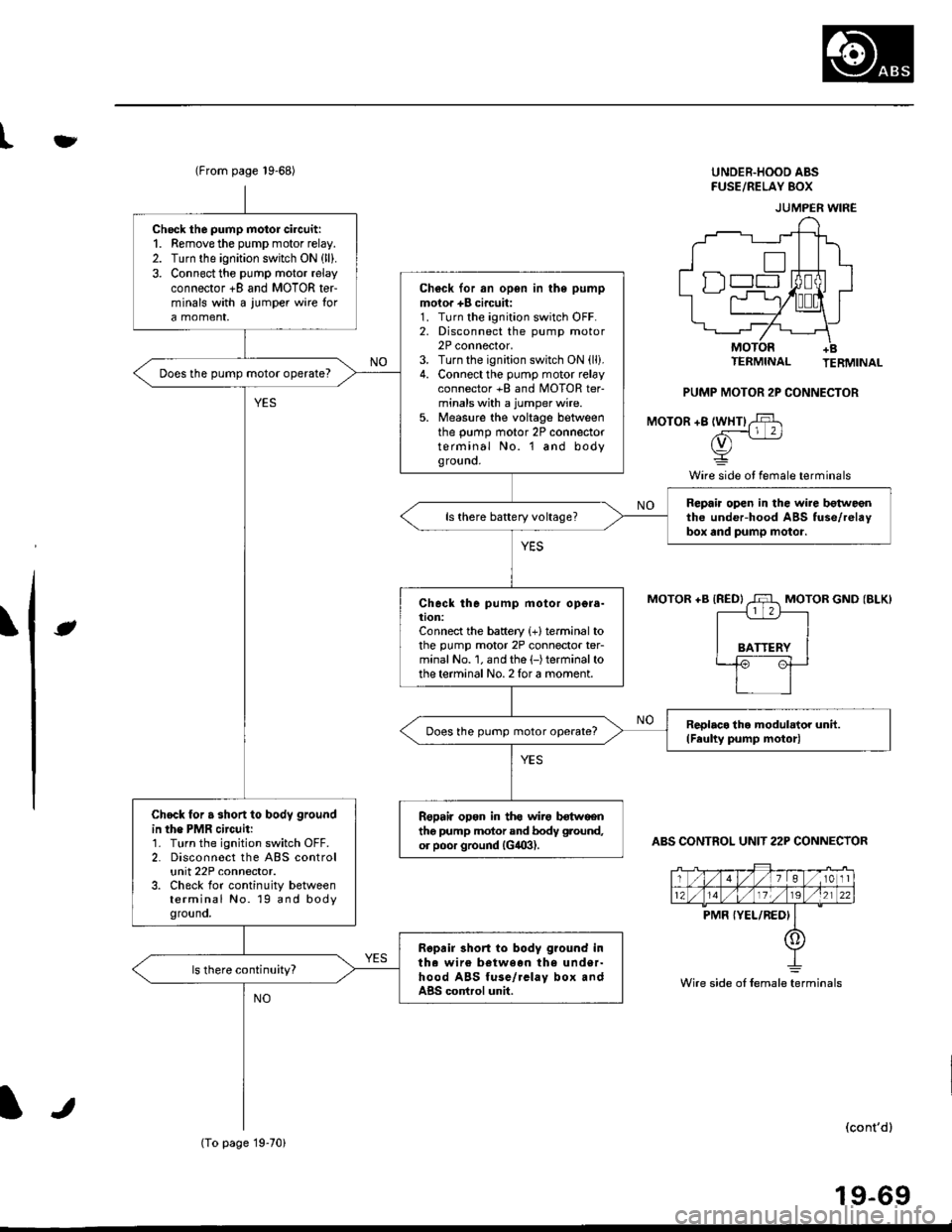
(From page 19-68)UNDER.HOOD ABSFUSE/RELAY 8()X
TERMINAL TERMINAL
PUMP MOTOR 2P CONNECTOR
MOTOR +8 lWHTl,$
rv) -
Y
Wire side ot female terminals
\lt
MOTOR +B {RED}MOTOR GND (BLK)
ABS CONTROL UNIT 22P CONNECTOR
(cont'dl
19-69
JUMPER WIRE
Wire side oI female terminals
Check the pump motor circuit:1. Remove the pump motor relay.2. Turn the ignition switch ON (ll).
3. Connect the pump motor relayconnector +8 and MOTOR terminals with a iumper wire tora momenr,
Ch€ck for an open in the pump
moior +B circuit:1. Turn the ignition switch OFF.2. Disconnect the pump motor2P connector,3. Turn the ignition switch ON (ll).
4. Connect the pump motor relayconnector +B and MOTOR ter-minals with a jumper wire.5. Measure the voltage betweenthe pump motor 2P connectorterminal No. l and bodyground.
Does the pump motor operate?
Repaia open in the wire botweentho under-hood ABS fuse/relaybox and pump motor.ls there battery voltage?
Check the pump motor opgra-tion:Connect the battery {+}terminal tothe pump motor 2P connector ter-minal No. 1. and the (-)terminalto
the terminal No. 2 for a moment.
ReDlaco lho modulator unit.(Feulty pump motor)Does the pump motor operate?
Chock for a short to body ground
in the PMR circuit:1. Turn the ignition switch OFF.2. Disconnect the ABS controlunit 22P connector.3. Check for continuity betweenterminal No. 19 and bodygrouno,
Repail opon in ths wirg botwgentho pump motor and bodv ground,
or poor ground (G,!09).
Ropair 3hort to body g?ound intha wire between the under-hood ABS fuse/rclay box andABS cortrol unit.
(To page 19-70)
Page 1223 of 2189

Troubleshooting
ABS Pump Motor (cont'dl
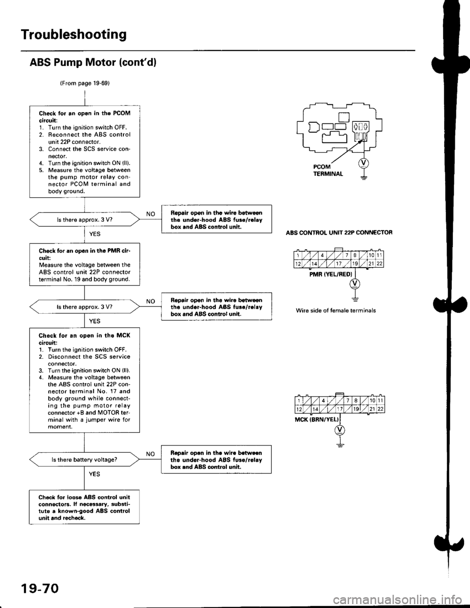
(From page 19-69)
ABS CONTROL UNIT 22P CONNECTOR
Check tor an opon in the PCOMcircuit:1. Turn the ignition switch OFF.2. Reconnect the ABS controlunit 22P connector.3. Connect the SCS service con-nector,4. Turn the ignition switch ON (ll).
5. Measure the voltage betweenthe pump motor relay connector PCOI,I terminal andbody ground.
Repair opon in tha wiro bEtwoonth. und€r-hood ABS fu3./rclsybox and ABS control unit.ls there approx. 3 V?
Chock for rn op6n in tho PMR cir-cuit:Measure the voltage beNveen theABS control unit 22P connectorterminal No. 19 and body ground.
Ropair opon in tho wira b€twoontho undor-hood ABS fu.e/rel.ybox and ABS control unit.ls there approx. 3 V?
Chock for an opon in ths MCKcircuh:1. Turn the ignition switch OFF.2- Disconnect the SCS serviceconnector.3. Turn the ignition switch ON lll).4. Measure the voltage betweenthe ABS control unit 22P con-nector terminal No. 17 andbody ground while connect-ing the pump motor relayconnector +8 and MOTOR ter'minal with a jumper wire formoment.
Repeir op.n in th. wire batweentho undor-hood ABS fu.o/rol.Vbox rnd ABS control unh.
Ch6ck lor loose ABS contlol unitconnoctors. lf ngc63ary, sub3ti-tute d known-good ABS controlunit and recheck.
n--l
wire side oI temale terminals
19-70
Page 1224 of 2189

tfMain Relay
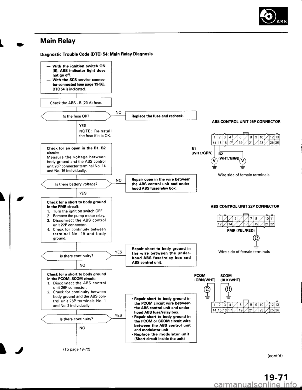
Diagnostic Trouble Code {DTC} 54: Msin Relay Diagnosis
YES
NOTE: Reinstallthe fuse if it is OK.
ABS CONTROL UNIT 26P CONNECTOR
Wire side of female terminals
ABS CONTROL UNIT 22P CONNECTOR
B1{WHT/GRNI
\e
PCOMIGRN/WHT}scoM{BLK/WHTI
(cont'd)
19-71
Wire side of female terminals
- With the ignition switch ON
{ll), ABS indic.tor light doesnot go off.- With the SCS 3ervica connoc-
tor connected (s€e pag€ 19-561,
DTC 54 is indicated.
checkthe ABS +B (20 Alfuse.
Replace th6 fuso and rechock.
Ch€ck for an op€n in the 81, 82
circuit:Measure the voltage betweenbody ground and the ABS control
unit 26P connector terminal No. '14
and No. 15 individually.
Repair open in the wire betweonthe ABS control unit and under-hood ABS tuse/relav box.
Check for a short lo body ground
in the PMR circuit:1- Turn the ignition switch OFF.
2. Remove the pump motor relay.
3. Disconnect the ABS controlunit 22P connector.4. Check for continuity betweenterminal No. 19 and bodygrouno.
Repair short to body ground in
the wire between the undor-hood ABS fuse/relay box andABS control unit.
ls there continuity?
Check tor a short to body ground
in the PCOM, SCOM circuit:1. Disconnect the ABS controlunit 26P connector.2. Check for continuity betweenbody ground and the ABS con-trol unit 26P terminals No. 1
and No.2 individually.
. Bepai. short to body ground in
tho PCOM circuit wire betwoenthe ABS control unit and under-hood ABS fu3e/.olay box.. Repair 3hort to body ground inthe PCOM or SCOM circuit wirebetween the ABS control unitand moduletor unit.. Rcplace th6 modulator unit.(Short circuit insido tho unit)
ls there continuity?
{To page 19 72)lr
Page 1225 of 2189
Troubleshooting
Main Relay (cont'd)
(From page 19'71)
PCOM(GRN/WHTIscoM(BLK/WHT}Check tor a short to powor in thePCOM, SCOM circuit:1. Turn the ignition switch ON r).2. Measure the voltage betweenbody ground and ABS controlunit 26P connector terminalsNo. l and No.2 individually.
. Repair 3hoit to power in ihercOM circuil wire bgtween theABS control unit end unde.-hood ABS fuse/relay box.. Repair sho to powor in thaPCOM oJ SCOM circuit wirobetwoen the ABS control unitand modulator unit.' Repl.co the modul.tor unit.lshort to Dowcr iGido the unit)Replace the ABS control unit.
Vo lta ge
19-72
Page 1226 of 2189
lgnition Voltage
Diagnostic Trouble Code (DTC) 61: lgnhion Voltage Diagno3is
A8S CONTROL UNIT 26P CONNECTOR
IG2IBLK/BLU}
]Wire side of lemale terminals
- With tha engin€ running, ABSindicator lighl is ON.- With the SCS s€rvice connec-to. conn€ctod ls€€ page 19-561,DTC 61 is indicated.
Problem v€rification:1. Erase the DTC.2. Start the engine.3. Make sure that the ABS ind;cator light comes on and DTC61 is indicated.
ls DTC 61 indicated?The system b OK .t this time.
Check the lG2 cilcuii:Measure the voltage between theABS control unit 26P connectorterminal No. 3 and body ground.
ls there 18 V or above?
lf the vohage is 0 V, check lor anopon in the lG2 circuit.It there is 12 - 17 V. substitute aknown-good ABS colrtrol unit andJecheck.
It
19-73
Page 1228 of 2189
\il
Modulator Unit
RemovaUlnstallation
CAUTION:
. Do not spill brake tluid on the car; it may damage the paint; it brako lluid does contact the paint, wash it off immedi-
ately with wator.
a Take care not to damage or delorm the brake lin€s during removal and installation.
. To prevent the brake tluid from tlowing, plug and cover the hose €nds and ioints with a shop tow6l or equivalent
mat€rial.
NOTE| Tightentheflare nutsto 15 N.m (1.5 kgnm. l1 lbf.ft).
Removal
'1. Disconnect the modulator unit 10P and Dump motor 2P connectors.
2. Disconnect the brake lines, then remove the modulator unit.
Installaiion
1. Install the modulator unit. then connect the brake lines.
2. Connect the modulator unit 10P and oumD motor 2P connectors.
3. Bleed the brake system.
4. Start the engine, and check that the ABS indicator light goes off.
Fomright-1461
PUMP MOTOR2P CONNECTOR
J
-R
/2e'
t'
TOR UNIT
tt
19-75
Page 1229 of 2189
ABS Control Unit
Pulsers/Wheel
Sensors
Replacement
1. Remove the right side kick panel.
2. Disconnect the ABS control unit connecrors.
3. Remove the ABS control unit,
4. lnstall the ABS control unit in the reverse order of
removal,
CONNECTORS
19-76
Inspection
Check the front and rear pulser for chipped or dam-aged teeth.
Measure the air gap between the wheel sensor andpulser all the way around while rotating the pulser.
Slandard: 0.4 - 1.0 mm (0.02 - 0.04 in,
NOTE; lf the gap exceeds 1.0 mm (0.04 in), theprobability is a distorted suspension arm which
should be replaced.
Dbc brake typo
0.{ - 1.0 mm(0.02 - 0.04 in)
Drum brake typ6
1.
Page 1230 of 2189
l}tWheel Sensor Replacement
NOTE:
. Becareful when installingthe sensors to avoid twisting the wires.
. The torque value of the bolts is 9.8 N.m (1.0 kgf.m, 7 lbf.ft).
Front
FRONT WHEEL SENSOR
Rear
1. Remove the hub bearing unit (see section 18).
2. Remove the four backing plate bolts.
3, Pull the backing plate away from the trailing arm, then remove the wheel sensor. lt is not necessary to disconnect the
brake line.
NOTE: This illustration is drum brake type. The torque value of the disk type is same as drum type.
REAR WHEEL SENSOR
J\
It
19-77