Page 1990 of 2189
100-2
Headlight Switch (cont'd)
-.I UNDER.DASHRom UderdashFur€/Bslay 8ox orprevrous prge.
- - -ri-Y c421 13 Y C5s1'- ll PHoro 63 ll esoro6J
neoialx I u/EW 50 BEDelfi i v'Edu7
'f ---- Hatchback l, Coupe and Sedan
c2o1 : I !'--'l Itlt5i:^- :i"'oYizt i i Iri"Je'tl
i l3pfif.l-"o."-i ".o,".*l =,a,e.Fema,e, ll L--J pe6161ja , ll terminals reversed
: tr_ _ _ _ _ _ _ _ _ _Y::_ _ _ _ _:
c202PNO|O 23ytEw 1
LEFTBRAKELIGHT/TAILLIGHTPage 110-5
9('99100 models 18)
FED/BLK
RIGHTTAILLIGHTPage 110-5
c562 .
vtEw42
c605
wEw a
RIGHTBRAKELIGHT/TAILLIGHTPage 110-5
LEFTLICENSEPLATELIGHTPage ! 10-5
for '99-'00 models
FUSE/RELAYBOX
1(cruise 3)c604 5
FEO/BLK
"ao,"a* |
I
/---lI \---t
LEFTTAILLIGHTPage 110-5
\;,,
LEFT FRONTPARKING/TURNSIGNALLIGHTPage 110-2
RIGHTLICENSEPLATELIGHTPage 110-5
,rUrOO ro.",. ?, I
r-\\_,
".,"-[TI
RIGHT FRONTPARKING/TURN SIGNALLIGHTPage 1l0-2
Page 1994 of 2189
License Lights, Parking Lights, and Taillights
- Coupe, Sedan, and Hatchback
I I rusecs I
Li5:_i
"^1,1fr!;?'
arr*
HI
UNDER.DASHFUSE/RELAYBOX
UNDER.HOOOFUSE/RELAYBOX
g€o Pow€rDlstrbutiofl,page 101?.
B1 YFED/GFN ll-- -
:t! - - - '--:gsg-l 3totur['JY3;tttu vehicres pre'wired tor
: -i::-- - - -. c;A (oPrroN) ceucssu'Yir
neoionlr lf C422 | Ptloro 56I PHorc 587 A, vtEw t6
-)' 56€. Hsadlqht I
FUsEsr lYi-"'l;-. I
:]% ropnor.rt cLlEssv'v .evu"rt JtJre"'
ru9c ltz DaO€ 10$1.uclrlaEtlclllS -
ta{- uotfls7.lla
c927 13 Y CssloPTfoN I ltlglo 63
clNl.rEcroR I
-" "'
tFEoiEL( |
II
v
To Daoe 110-3(AliC6upes and '96- 98 Sedans),or page 1 10-4 ( 99- 00 Sedans),or page 110-5 (Halchback)
FED/8LK
1(with cruise 3)
RED/BLI(
GAN/YEI
AED/ELX'99100
moqelsc202r -'! wiiri| | xtYess
I I EntryI
KEYLESS '
DOORLOCK :CONTROL ;UNIT
RIGHT FRONTPARKING/TURNSIGNAL LIGHT
L.-r
/-1M LEFT FRONTfb d I PARKTNGIuRN
\Y,Z slcNAL LlcHr
'I
see Ground
"* | 3$l''Tll
II
l.?'J
! czoz- PHOfa 19
110-2
Page 1998 of 2189
Turn Signal and Hazard Warning Lights
- All except'99-'00 Sedans
c411PHOTO 60vlEw 60
15
5
see uLights
T*x ll
_1
55
L
tBlFED/BLX
I
c501
vtEw 5!
IL
FED/B
Dash
UNDER.OASHFUSE/BELAYBOX
HAZARDWARNINGswtTcHvtEw 32
See GroundD$tribution,page l4-7.
----J
See Ground Distribution,wge 14-7.
GAN/OFN
GAUGEASSEMBLY
IndicatorsL-------i82ALKI
I ffi"ufi:I'oo
It
tl
L___l#: G401PHOfO 5/
TUHIISIGNAUHAZARDREI-AV?nofo g
:n-
PHOfO 57
l:r---
-";;r";;;------"-.";:l[-;.:r
?EEi *,.:ffi -l
t """."1 .V _]z_"*.-l le?.:*"
To under-dash GFN RED
| -".r"-.'Frl*-?il, I
5iiil3"J:Ui* ., L
ReravBoxonracinspase4
I
I I LEFT TURI{ I FIGHTTURN I
i @iJ8l$,o" @tSS'* i
3""",n",, IH TH
l{azAioU'AN GSW|TCHUGHT
110-6
Page 1999 of 2189

\
*=l\4ale-Female
terminals reversedfor'99-'00 models
TumSignalSwitch
From Splice orfacing page.
v
icnrineo I csor
" l"P'li'?c--
l
'f "*f B""i.Bfii'Jr'l ".^f
I see Grouno ar-< pay6!,,-,v >-ra
'|
Tt""""i*l}=J'..""."'.*�i{{?;:*
k::
*-i;,
f#::*=i
COMBINATIONLIGHTswtTcH
c423
vtEw 3
From Splice onfacing page.
v
ilo"nntt | "uo,
n I�',tr[T?'*
UNDER.DASH
I
I
/7-T LEFr FRoNr /A LEFr REAR ./A nrcxr neanI p q I PARKING/TURN I le I TURNSIGNAL I b ITURNSIGNAL
\:9./ srcNAL LrcHr \!r/ uorr r ,/ LrcHr
Y2See Ground erx IDistnbution, Ipages 14-10 >-rOand 14-12. I"'-
I 3:"":ix'5: "'iI
."oo
and 1+12 "I
I ."n.
aLK
I FUSE/RELAY
iF,?|",,
c421
vtEw50\-----'if,
u';%- l-t?'o' 10
o""n.. I
u't* o' cFN,yEL
,ol
('ee- oo moders except Cliti I{96j98 Sedans excepl GX 16} A C562. l---- -'f,
t:;?,''
o"n,^r.. I .BN'YEL
c6o4 , 1..0.'iftr",'::"""^,,, i "^1,T?l:i""."".
Onrl,rer- |
l1
L.tI
ru Y Lx%", s""1, 15
o"n, I
u't" uo
GRNTRED*"1
"
l riqrk" 1,so-,sa seoans111
ru
| aEo/BLK .""
o"n'"]
,lrtrufli'""""
c201
vtEw 30
FED/BLXSeeParkingLights
!t c2o2 4 c6ol- PHOTO 19 - PHA|A 1A2PHOIO 173 (Halchback)
110-7
Page 2000 of 2189
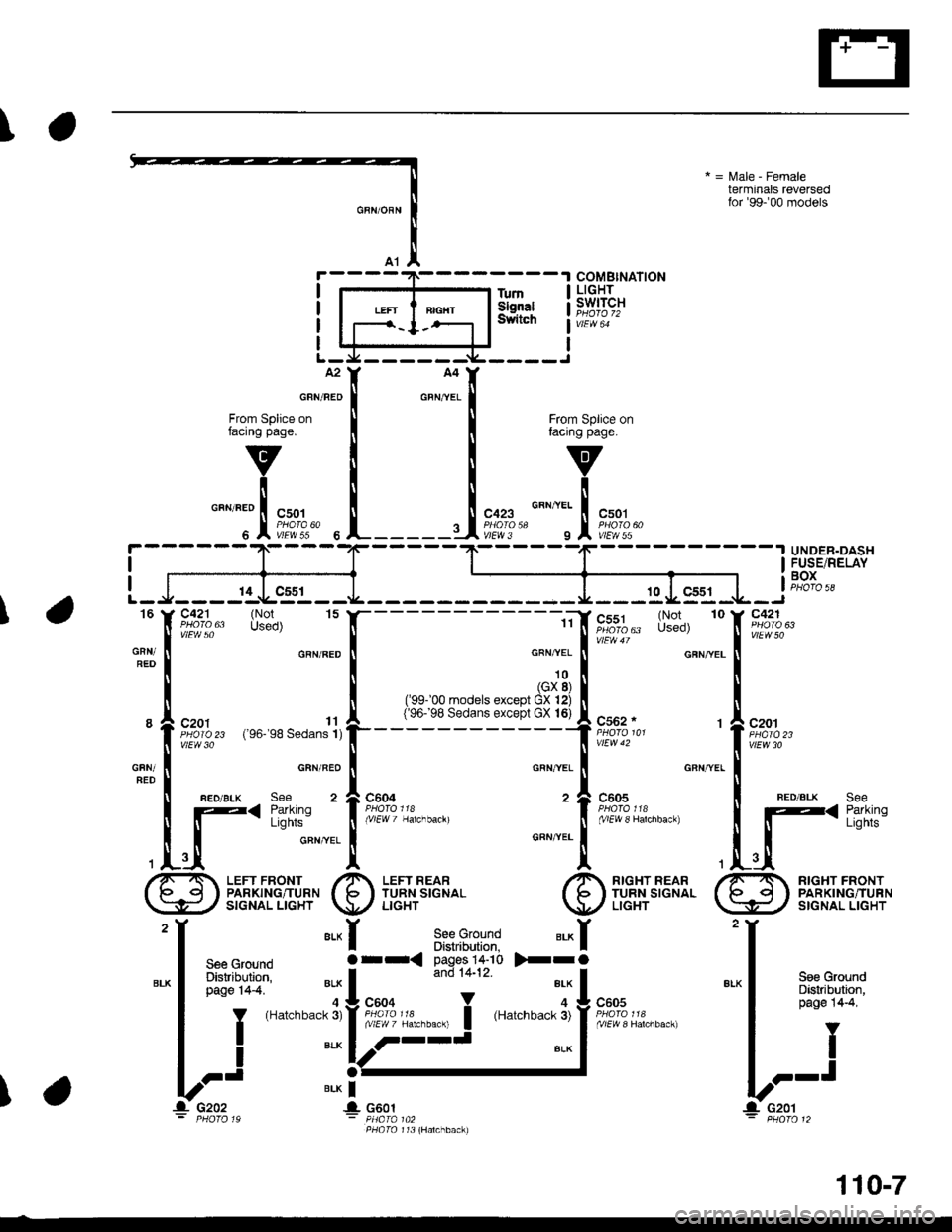
Turn Signal and Hazard Warning Lights
- '99-'00 Sedans
@
i-f;.;l H33'""
i)ir- ilEtFfLJL---J Box
3 Y c352 PHoro 7
vlEw 27
c411PHOfO @vlEw 60
I UNDER.I DASH: FUSE/tunSIGIITJTOAZARDR€I.AYpsalo I
I RELAYI BOXi PHO|O 58
S€e Ground Disldbution,pag€ l4-7.--------Jc501
S€€ GroundDistih.dion,pag€ 14-7.
vtEw 55
s2ALK
S€e g.ound Dist$bution,pag€ t4-7,
HAZARDWARNINGswtTcHvtEw 32
'--{
To UnderdashFuse/Relay Boxon this page.
SeeGauggs,lndicato.sL-----
GAUGEASSEMBLY
I
I ff;f#looo
ll
L___l+: G401PHOfO 57
""k
PHO|O 57
1 10-8
Page 2001 of 2189
\
COMBINATIONLIGHTswrTcH
ytEW 64
TumSignalSwltctl
A2
From Splice onfacing page.
v
i
cazs o"nttt I csor';l:J?'" " l'El?,*{
GRN/FED
606UNDER-DASH
IIFUSE/RELAYi BoxI
I
ffi **;r',''-"'
"
"'J- *.. 1
t*?'1,"
rzl I
-or{n9"',, '*t?%,,
;v1Fw4' il
!/fwJo
- t -- | REo alK seecFNYEL
I
GFNYEL
I l_< i,tlll,
I tt2x 'r-lf
7 nrcxr nean /-T RrcHr FRoNrI b ITURNSIGNAL I|o q I PARKINGiTURN
\U/ LrcHr \:9,/ srcNAL LrcHr
'r 'r
tt
""1 I g:"',gn*l*
I
"'*
I Pase 144
I tI-l
V?'t
+ 9ao-1
L-J---11J.gs-l---
!- c2o2 ! c6o1- e4ofo ,9 - Phata t t3PHA|A 142 (GX)
'I tI
seecround
I 8:":'Bn# I 3:lj:i"lll:
""
|
''T" *1..--I
V-' "'*f-
16 Y C421 (Not Used) 15
"*:
[
;'m::' .FN'BED
t l g,a%,, ro*'lr
i
""'o
GFNTRED
c"" I REo,BLK see"'o
I F< lffli:'
,tr_{ 2
/-T LEFr FRoNr fi lerrneaaI Io €l I PARKING/TURN I 15 | TURN SIGNAL\l=E: / srcNALLrcHr \U,/ LrcHr
I
110-9
Page 2006 of 2189

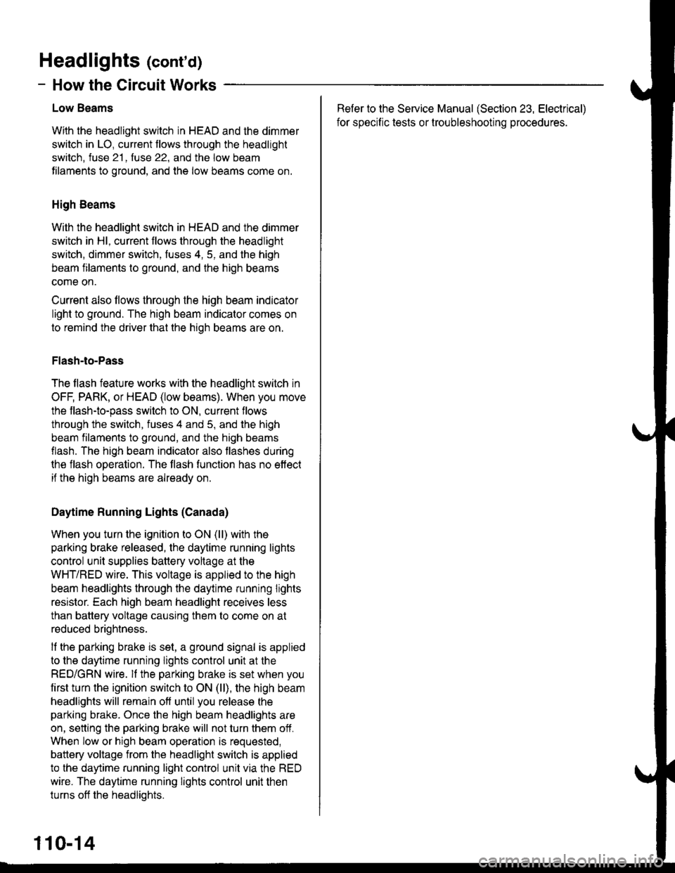
Headlights (cont'd)
- How the Circuit Works
Low Beams
With the headlight switch in HEAD and the dimmer
switch in LO, current tlows through the headlight
switch. fuse 21 . fuse 22. and the low beam
tilaments to ground, and the low beams come on.
High Beams
With the headlight switch in HEAD and the dimmer
switch in Hl, current flows through the headlight
switch, dimmer switch, fuses 4, 5, and the high
beam filaments to ground, and the high beams
come on.
Current also llows through the high beam indicator
light to ground. The high beam indicator comes on
to remind the driver that the high beams are on.
Flash-to-Pass
The flash feature works with the headlight switch in
OFF, PARK, or HEAD (low beams). When you move
the flash-to-pass switch to ON, current flows
through the switch, fuses 4 and 5, and the high
beam filaments to ground, and the high beams
flash. The high beam indicator also flashes during
the flash operation. The flash function has no effect
if the high beams are already on
Daytime Running Lights (Canada)
When you turn the ignition to ON (ll) with the
parking brake released, the daytime running lights
control unit supplies battery voltage at the
WHT/RED wire. This voltage is applied to the high
beam headlights through the daytime running lights
resistor. Each high beam headlight receives less
than battery voltage causing them to come on at
reduced brightness.
lf the parking brake is set, a ground signal is applied
to the daytime running lights control unit at the
RED/GRN wire. lf the parking brake is set when you
first turn the ignition switch to ON (ll), the high beam
headlights will remain off until you release the
parking brake. Once the high beam headlights are
on, setting the parking brake will not turn them ofi.
When low or high beam operation is requested,
battery voltage from the headlight switch is applied
to the daytime running light control unit via the RED
wire. The daytime running lights control unit then
turns off the headlights.
Refer to the Service Manual (Section 23, Electrical)
for specific tests or lroubleshootrng procedures.
110-14
Page 2026 of 2189

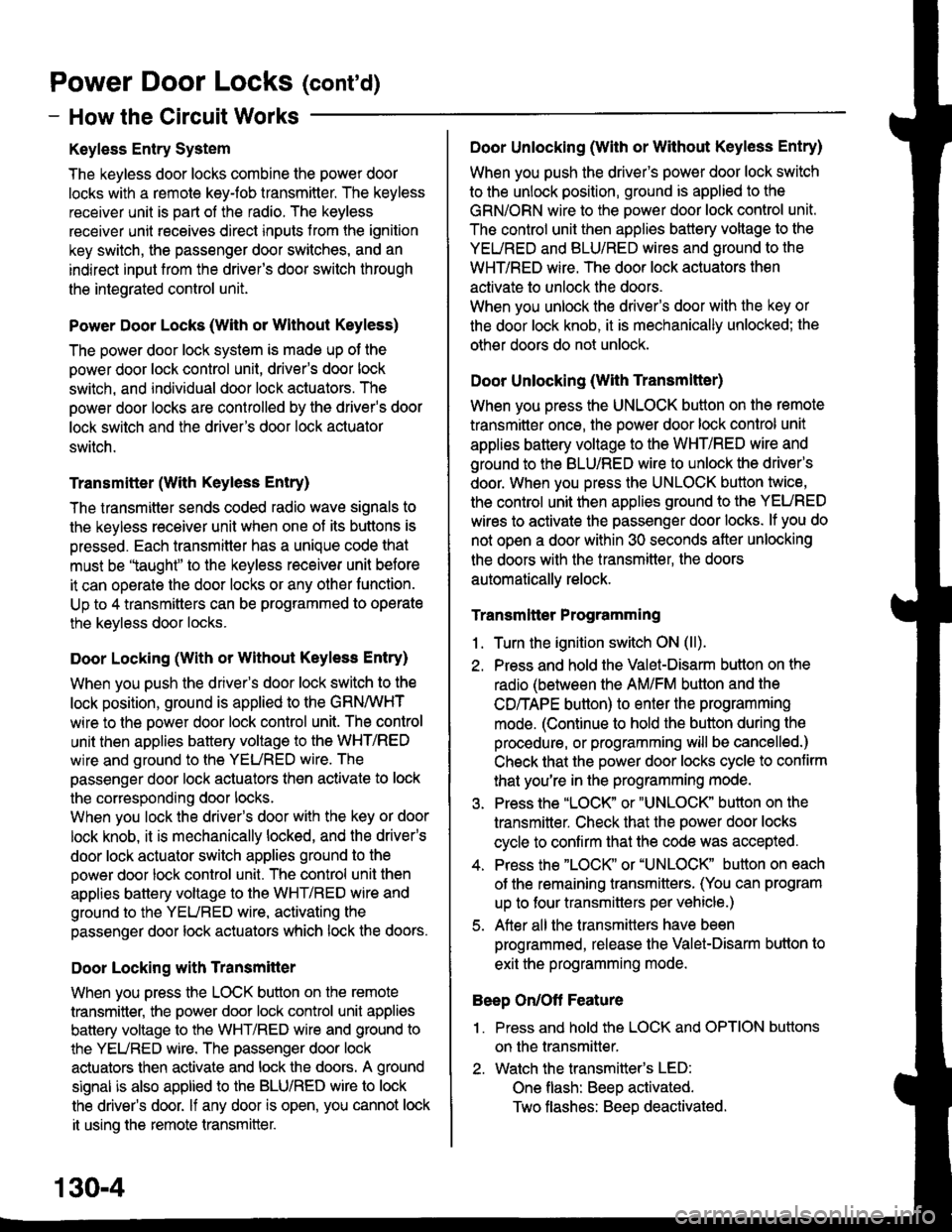
Power Door Locks (cont'd)
- How the Circuit Works
Keyless Entry System
The keyless door locks combine the power door
locks with a remote keyJob transmitter. The keyless
receiver unit is part of the radio. The keyless
receiver unit receives direct inputs f rom the ignition
key switch, the passenger door switches, and an
indirect input trom the driver's door switch through
the integrated control unit.
Power Door Locks (With or Wlthout Keyless)
The power door lock system is made up of the
oower door lock control unit. driver's door lock
switch, and individual door lock actuators. The
power door locks are controlled by the driver's door
lock switch and the driver's door lock actuator
switch.
Transmitter (With Keyless Entry)
The transmitter sends coded radio wave signals to
the keyless receiver unit when one ot its buttons is
pressed. Each transmitter has a unique code that
must be 'laught" to the keyless receiver unit before
it can operate the door locks or any other lunction.
Up to 4 transmitters can be programmed to operate
the keyless door locks.
Door Locking (With or without Keyless Entry)
When you push the driver's door lock switch to the
lock position, ground is applied to the GBN/IVHT
wire to the oower door lock control unit. The control
unit then applies battery voltage to the WHT/RED
wire and ground to the YEURED wire. The
passenger door lock actuators then activate to lock
the corresponding door locks.
When you lock the driver's door with the key or door
lock knob, it is mechanically locked, and the driver's
door lock actuator switch applies ground to the
oower door lock control unit. The control unit then
applies battery voltage to the WHT/RED wire and
ground to the YEURED wire, activating the
passenger door lock actuators which lock the doors.
Dool Locking with Transmitter
When you press the LOCK button on the remote
transmitter, the power door lock control unit applies
battery voltage to the WHT/RED wire and ground to
the YEURED wire. The passenger door lock
actuators then activate and lock the doors. A ground
slgnal is also applied to the BLU/RED wire to lock
the driver's door. lf any door is open, you cannot lock
it using the remote transmitter.
Door Unlocking (With or Without Keyless Entry)
When you push the driver's power door lock switch
to the unlock position, ground is applied to the
GRN/ORN wire to the power door lock control unit.
The control unit then applies battery voltage to the
YEURED and BLU/RED wires and ground to the
WHT/RED wire. The door lock actuators then
activate to unlock the doors.
When you unlock the driver's door with the key or
the door lock knob, it is mechanically unlocked; the
other doors do not unlock.
Door Unlocking (With Transmltter)
When you press the UNLOCK button on lhe remote
transmitter once. the power door lock control unit
applies battery voltage to the WHT/RED wire and
ground to the BLU/RED wire to unlock the driver's
door. When you press the UNLOCK button twice,
the control unit then applies ground to the YEURED
wires to activate the passenger door locks. lf you do
not open a door within 30 seconds after unlocking
the doors with the transmitter, the doors
automatically relock.
Transmltter Programming
1 . Turn the ignition switch ON (ll).
2. Press and hold the Valet-Disarm button on the
radio (between the AM/FM button and the
CD/TAPE button) to enter the programming
mode. (Continue to hold the button during the
procedure, or programming will be cancelled.)
Check that the power door locks cycle to confirm
that you're in the programming mode.
3. Press the "LOCK' or "UNLOCK' button on the
transmitter. Check that the power door locks
cycle to confirm that the code was accepted.
4. Press the "LOCK" or "UNLOCK" button on each
of the remaining transmitters. (You can program
up to four transmitters per vehicle.)
5. After all the transmitters have been
programmed, release lhe Valet-Disarm button to
exit the programming mode.
Beep On/Oft Feature
'I . Press and hold the LOCK and OPTION buttons
on the transmitter.
2. Watch the transmitter's LED:
One flash: Beeo activated.
Two tlashes: Beeo deactivated.
130-4