Page 222 of 338
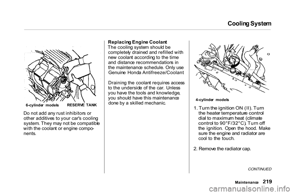
Coolin
g Syste m
D o no t ad d an y rus t inhibitor s o r
othe r additive s t o you r car' s coolin g
system . The y ma y no t b e compatibl e
wit h th e coolan t o r engin e compo -
nents .
Replacin
g Engin e Coolan t
Th e coolin g syste m shoul d b e
completel y draine d an d refille d wit h
ne w coolan t accordin g t o th e tim e
an d distanc e recommendation s i n
th e maintenanc e schedule . Onl y us e
Genuin e Hond a Antifreeze/Coolant .
Drainin g th e coolan t require s acces s
t o th e undersid e o f th e car . Unles s
yo u hav e th e tool s an d knowledge ,
yo u shoul d hav e thi s maintenanc e
don e b y a skille d mechanic . 4-cylinde
r model s
1 . Tur n th e ignitio n O N (II) . Tur n
th e heate r temperatur e contro l
dia l t o maximu m hea t (climat e
contro l t o 90°F/32°C) . Tur n of f
th e ignition . Ope n th e hood . Mak e
sur e th e engin e an d radiato r ar e
coo l t o th e touch .
2 . Remov e th e radiato r cap .
CONTINUED
Maintenanc e
6-cylinde
r model sRESERV
E TAN K
Page 225 of 338

Coolin
g Syste m
5 . Whe n th e coolan t stop s draining ,
tighte n th e drai n plu g a t th e
botto m o f th e radiator .
6 . 4-cylinder models
Pu t a ne w washe r o n th e drai n bolt ,
the n reinstal l th e drai n bol t i n th e
engin e block . Tighte n it securely .
Tightenin g torque :
6 1 lbf.ft(83N .
m,8.5kgf.m )
6-cylinder models
Tighte n th e drai n bol t a t th e rea r
o f th e engin e cylinde r bloc k
securely .
Tightenin g torque :
7 lbf.f t (1 0 N .
m , 1. 0 kgf.m )
7
. Mi x th e recommende d antifreez e
wit h a n equa l amoun t o f purifie d
o r distille d wate r i n a clea n
container . Th e coolin g syste m
capacit y is :
4-cylinder models
With 5-speed manual transmission:
1.4
5 U S ga l (5. 5 ,1.2 1 Im p gal )
With automatic transmission:
1.4
3 U S ga l (5. 4 ,1.1 9 Im p gal )
6-cylinder models
1.4
8 U S ga l (5. 6 ,1.2 3 Im p gal )
8.
4-cylinder models
Loose n th e bleede r bol t o n to p o f
th e engine .
Pou r coolan t int o th e radiator .
Tighte n th e bleede r bol t whe n
coolan t come s ou t i n a stead y
strea m wit h n o bubbles .
Maintenanc e
BLEEDE
R BOL T
Page 226 of 338
Coolin
g Syste m
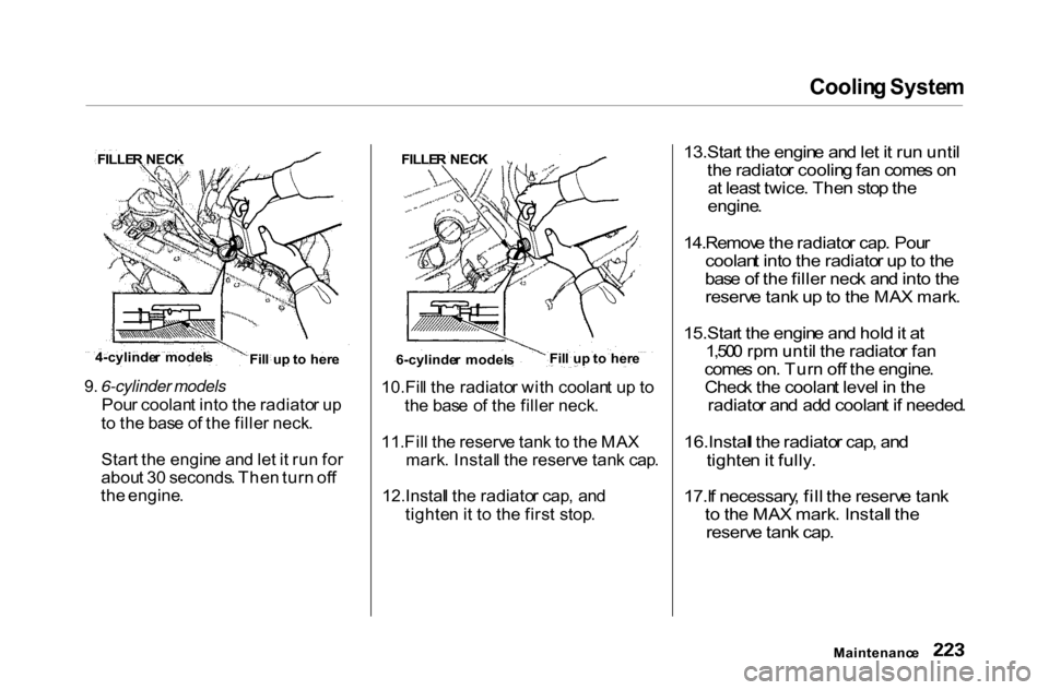
9 . 6-cylinder models
Pou r coolan t int o th e radiato r u p
t o th e bas e o f th e fille r neck .
Star t th e engin e an d le t i t ru n fo r
abou t 3 0 seconds . The n tur n of f
th e engine . 10.Fil
l th e radiato r wit h coolan t u p t o
th e bas e o f th e fille r neck .
11 .Fil l th e reserv e tan k t o th e MA X
mark . Instal l th e reserv e tan k cap .
12.Instal l th e radiato r cap , an d
tighte n it t o th e firs t stop .
13.Star
t th e engin e an d le t i t ru n unti l
th e radiato r coolin g fa n come s o n
a t leas t twice . The n sto p the
engine .
14.Remov e the radiato r cap . Pou r
coolan t int o the radiato r u p to th e
bas e o f the fille r nec k an d int o th e
reserv e tan k u p to th e MA X mark .
15.Star t th e engin e an d hol d it a t
1,50 0 rp m unti l the radiato r fa n
come s on . Tur n of f the engine .
Chec k th e coolan t leve l i n the
radiato r an d ad d coolan t i f needed .
16.Instal l th e radiato r cap , an d
tighte n it fully .
17.I f necessary , fil l the reserv e tan k
t o th e MA X mark . Instal l the
reserv e tan k cap .
Maintenanc e
FILLE
R NEC K FILLER NEC K
Fill u p to her e
6-cylinde r model s
4-cylinde
r model s
Fill u p to her e
Page 229 of 338
Transmissio
n Flui d
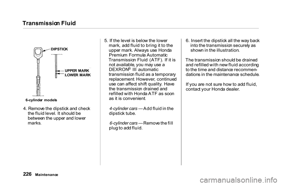
4 . Remov e th e dipstic k an d chec k
th e flui d level . I t shoul d b e
betwee n th e uppe r an d lowe r
marks .
5
. I f th e leve l i s belo w th e lowe r
mark , ad d flui d t o brin g it t o th e
uppe r mark . Alway s us e Hond a
Premiu m Formul a Automati c
Transmissio n Flui d (ATF) . I f i t i s
no t available , yo u ma y us e a
DEXRON
®
III automatic
transmissio n flui d a s a temporar y
replacement . However , continue d
us e ca n affec t shif t quality . Hav e
th e transmissio n draine d an d
refille d wit h Hond a AT F a s soo n
a s it i s convenient .
4-cylinder cars — Ad d flui d in th e
dipstic k tube .
6-cylinder cars — Remov e th e fil l
plu g to ad d fluid . 6
. Inser t th e dipstic k al l th e wa y bac k
int o th e transmissio n securel y a s
show n in th e illustration .
Th e transmissio n shoul d b e draine d
an d refille d wit h ne w flui d accordin g
t o th e tim e an d distanc e recommen -
dation s in th e maintenanc e schedule .
I f yo u ar e no t sur e ho w to ad d fluid ,
contac t you r Hond a dealer .
Maintenanc e
DIPSTIC
K
UPPE R MAR K
LOWE R MAR K
6-cylinde r model s
Page 231 of 338
Brak
e an d Clutc h Flui d
Chec k th e flui d leve l i n th e reser -
voir s monthly . Ther e ar e u p to tw o
reservoirs , dependin g o n th e model .
The y are :
Brak e flui d reservoi r (al l models )
Clutc h flui d reservoi r
(manua l transmissio n only )
Th e brak e flui d shoul d b e replace d
accordin g to th e tim e an d distanc e
recommendation s in th e mainte-
nanc e schedule . Alway
s us e Genuin e Hond a DO T 3
brak e fluid . I f i t i s no t available , yo u
shoul d us e onl y DO T 3 o r DO T 4
fluid , fro m a seale d container , a s a
temporar y replacement . However ,
th e us e o f an y non-Hond a brak e flui d
ca n caus e corrosio n an d decreas e
th e lif e o f th e system . Hav e th e
brak e syste m flushe d an d refille d
wit h Hond a DO T 3 brak e flui d a s
soo n a s possible .
Brak e flui d marke d DO T 5 is no t
compatibl e wit h you r car' s brakin g
syste m an d ca n caus e extensiv e
damage .
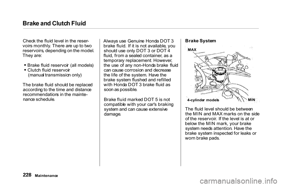
Brak
e Syste m
Th e flui d leve l shoul d b e betwee n
th e MI N an d MA X mark s o n th e sid e
o f th e reservoir . I f th e leve l i s a t o r
belo w th e MI N mark , you r brak e
syste m need s attention . Hav e th e
brak e syste m inspecte d fo r leak s o r
wor n brak e pads .
Maintenanc e 4-cylinde
r model s MI
N
MA
X
Page 234 of 338
Ai
r Cleane r Elemen t
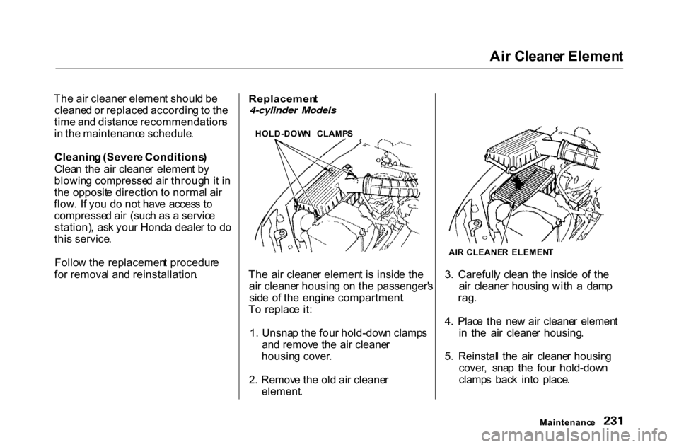
Th e ai r cleane r elemen t shoul d b e
cleane d o r replace d accordin g to th e
tim e an d distanc e recommendation s
i n th e maintenanc e schedule .
Cleanin g (Sever e Conditions )
Clea n th e ai r cleane r elemen t b y
blowin g compresse d ai r throug h i t i n
th e opposit e directio n t o norma l ai r
flow . I f yo u d o no t hav e acces s t o
compresse d ai r (suc h a s a servic e
station) , as k you r Hond a deale r t o d o
thi s service .
Follo w th e replacemen t procedur e
fo r remova l an d reinstallation .
Replacemen
t
4-cylinder Models
HOLD-DOW N CLAMP S
Th e ai r cleane r elemen t i s insid e th e
ai r cleane r housin g o n th e passenger' s
sid e o f th e engin e compartment .
T o replac e it :
1 . Unsna p th e fou r hold-dow n clamp s
an d remov e th e ai r cleane r
housin g cover .
2 . Remov e th e ol d ai r cleane r
element . 3
. Carefull y clea n th e insid e o f th e
ai r cleane r housin g wit h a dam p
rag .
4 . Plac e th e ne w ai r cleane r elemen t
i n th e ai r cleane r housing .
5 . Reinstal l th e ai r cleane r housin g
cover , sna p th e fou r hold-dow n
clamp s bac k int o place .
Maintenanc e
AI
R CLEANE R ELEMEN T
Page 236 of 338
Hoo
d Latch , Spar k Plug s (4-cylinde r Models )
Clea n th e hoo d latc h assembl y wit h a
mil d cleaner , the n lubricat e it wit h a
multipurpos e grease . Lubricat e al l
th e movin g parts , includin g th e pivot .
T o lubricat e them , remov e th e
holdin g cli p an d pul l th e cove r away .
Follo w th e tim e an d distanc e
recommendation s i n th e
Maintenanc e Schedule . I f yo u ar e
no t sur e ho w to clea n an d greas e th e
latch , contac t you r Hond a dealer . Spar
k Plug s
Th e spar k plug s i n you r ca r shoul d
b e replace d accordin g to th e tim e
an d distanc e recommendation s in
th e maintenanc e schedule .
Replacement
SPARK PLU G CA P
1 . Clea n u p an y dir t an d oi l aroun d
th e spar k plu g caps .
2 . Remov e th e spar k plu g ca p b y
pullin g i t straigh t out .
3 . Remov e th e spar k plu g wit h
a five-eighth s inc h (1 6 mm ) spar k
plu g socket .
CONTINUED
Maintenanc e
Hoo
d Latc h
LATC H ASSEMBL Y
PIVOT S
Page 238 of 338
Spar
k Plug s (6-cylinde r Models )
Th e spar k plug s in you r ca r shoul d
b e replace d accordin g to th e tim e
an d distanc e recommendation s i n
th e maintenanc e schedule .
Replacement
HOLDING CLI P
1 . Loose n th e tw o holdin g clip s b y
turnin g th e head s one-quarte r tur n
counterclockwis e wit h a flat-tippe d
screwdriver . Remov e th e cove r o n
th e fron t cylinde r ban k b y pullin g
i t straigh t up . 2
. Clea n u p an y dir t an d oi l tha t hav e
collecte d aroun d th e ignitio n coils .
3 . Disconnec t th e wir e connecto r
fro m th e ignitio n coi l b y pushin g
o n th e loc k ta b an d pullin g o n th e
connector . Pul l o n th e plasti c
connector , no t th e wires .
CONTINUED
Maintenanc e