Page 183 of 280
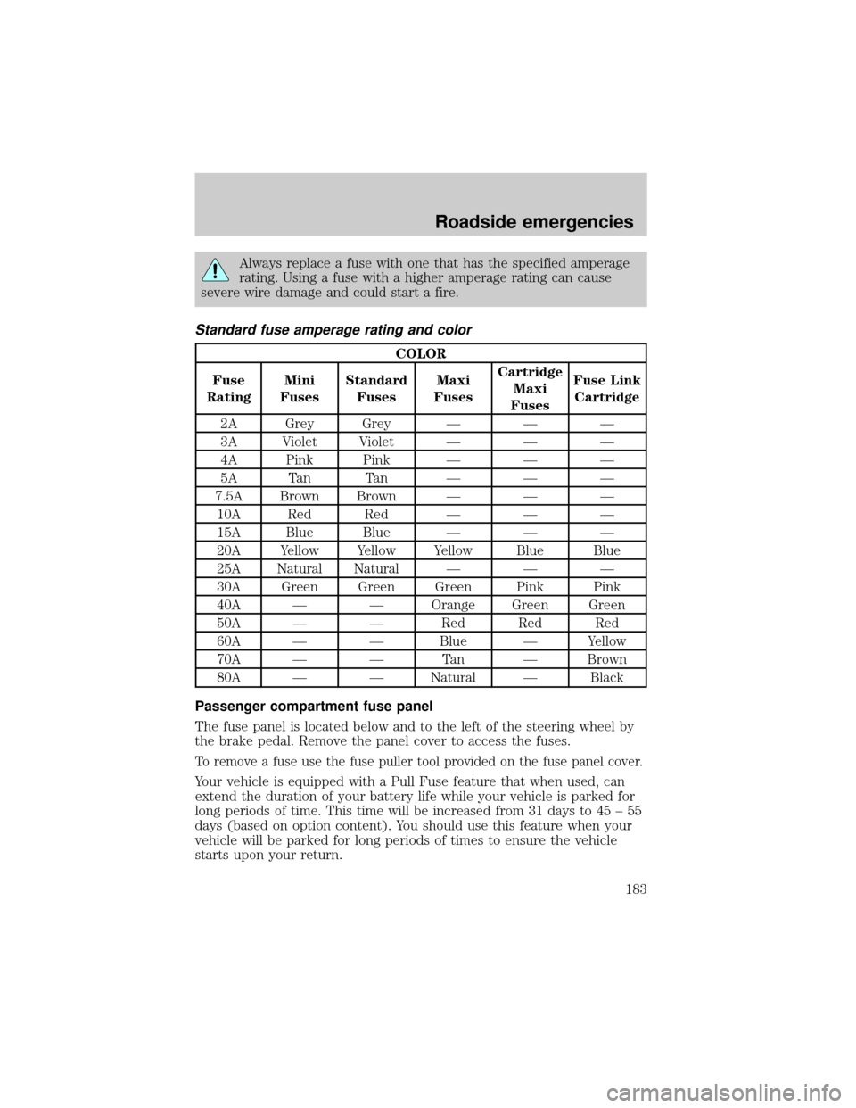
Always replace a fuse with one that has the specified amperage
rating. Using a fuse with a higher amperage rating can cause
severe wire damage and could start a fire.
Standard fuse amperage rating and color
COLOR
Fuse
RatingMini
FusesStandard
FusesMaxi
FusesCartridge
Maxi
FusesFuse Link
Cartridge
2A Grey Grey Ð Ð Ð
3A Violet Violet Ð Ð Ð
4A Pink Pink Ð Ð Ð
5A Tan Tan Ð Ð Ð
7.5A Brown Brown Ð Ð Ð
10A Red Red Ð Ð Ð
15A Blue Blue Ð Ð Ð
20A Yellow Yellow Yellow Blue Blue
25A Natural Natural Ð Ð Ð
30A Green Green Green Pink Pink
40A Ð Ð Orange Green Green
50A Ð Ð Red Red Red
60A Ð Ð Blue Ð Yellow
70A Ð Ð Tan Ð Brown
80A Ð Ð Natural Ð Black
Passenger compartment fuse panel
The fuse panel is located below and to the left of the steering wheel by
the brake pedal. Remove the panel cover to access the fuses.
To remove a fuse use the fuse puller tool provided on the fuse panel cover.
Your vehicle is equipped with a Pull Fuse feature that when used, can
extend the duration of your battery life while your vehicle is parked for
long periods of time. This time will be increased from 31 days to 45 ± 55
days (based on option content). You should use this feature when your
vehicle will be parked for long periods of times to ensure the vehicle
starts upon your return.
Roadside emergencies
183
Page 186 of 280
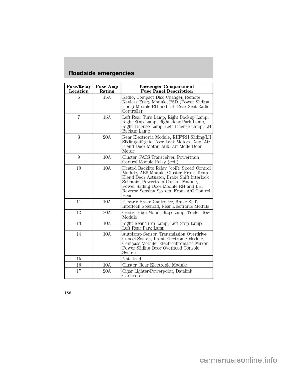
Fuse/Relay
LocationFuse Amp
RatingPassenger Compartment
Fuse Panel Description
6 15A Radio, Compact Disc Changer, Remote
Keyless Entry Module, PSD (Power Sliding
Door) Module RH and LH, Rear Seat Radio
Controller
7 15A Left Rear Turn Lamp, Right Backup Lamp,
Right Stop Lamp, Right Rear Park Lamp,
Right License Lamp, Left License Lamp, LH
Backup Lamp
8 20A Rear Electronic Module, RHF/RH Sliding/LH
Sliding/Liftgate Door Lock Motors, Aux. Air
Blend Door Motor, Aux. Air Mode Door
Motor
9 10A Cluster, PATS Transceiver, Powertrain
Control Module Relay (coil)
10 10A Heated Backlite Relay (coil), Speed Control
Module, ABS Module, Cluster, Front Temp
Blend Door Actuator, Brake Shift Interlock
Solenoid, Powertrain Control Module,
Power Sliding Door Module RH and LH,
Reverse Sensing System, Front A/C Control
Head
11 10A Electric Brake Controller, Brake Shift
Interlock Solenoid, Rear Electronic Module
12 20A Center High-Mount Stop Lamp, Trailer Tow
Module
13 10A Right Rear Turn Lamp, Left Stop Lamp,
Left Rear Park Lamp
14 10A Autolamp Sensor, Transmission Overdrive
Cancel Switch, Front Electronic Module,
Compass Module, Electrochromatic Mirror,
Power Sliding Door Overhead Console
Switch
15 Ð Not Used
16 10A Cluster, Rear Electronic Module
17 20A Cigar Lighter/Powerpoint, Datalink
Connector
Roadside emergencies
186
Page 190 of 280
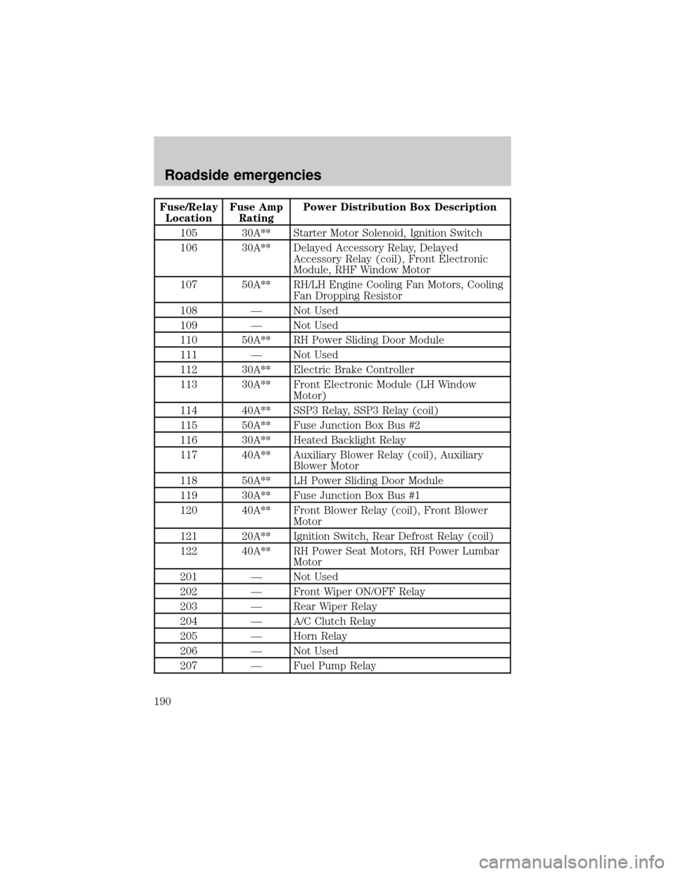
Fuse/Relay
LocationFuse Amp
RatingPower Distribution Box Description
105 30A** Starter Motor Solenoid, Ignition Switch
106 30A** Delayed Accessory Relay, Delayed
Accessory Relay (coil), Front Electronic
Module, RHF Window Motor
107 50A** RH/LH Engine Cooling Fan Motors, Cooling
Fan Dropping Resistor
108 Ð Not Used
109 Ð Not Used
110 50A** RH Power Sliding Door Module
111 Ð Not Used
112 30A** Electric Brake Controller
113 30A** Front Electronic Module (LH Window
Motor)
114 40A** SSP3 Relay, SSP3 Relay (coil)
115 50A** Fuse Junction Box Bus #2
116 30A** Heated Backlight Relay
117 40A** Auxiliary Blower Relay (coil), Auxiliary
Blower Motor
118 50A** LH Power Sliding Door Module
119 30A** Fuse Junction Box Bus #1
120 40A** Front Blower Relay (coil), Front Blower
Motor
121 20A** Ignition Switch, Rear Defrost Relay (coil)
122 40A** RH Power Seat Motors, RH Power Lumbar
Motor
201 Ð Not Used
202 Ð Front Wiper ON/OFF Relay
203 Ð Rear Wiper Relay
204 Ð A/C Clutch Relay
205 Ð Horn Relay
206 Ð Not Used
207 Ð Fuel Pump Relay
Roadside emergencies
190
Page 191 of 280
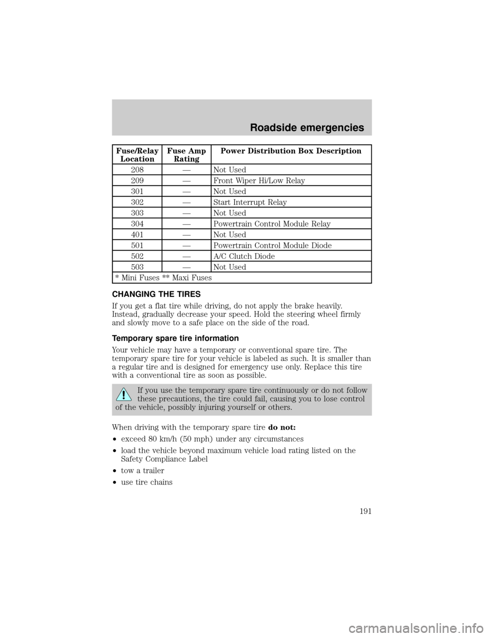
Fuse/Relay
LocationFuse Amp
RatingPower Distribution Box Description
208 Ð Not Used
209 Ð Front Wiper Hi/Low Relay
301 Ð Not Used
302 Ð Start Interrupt Relay
303 Ð Not Used
304 Ð Powertrain Control Module Relay
401 Ð Not Used
501 Ð Powertrain Control Module Diode
502 Ð A/C Clutch Diode
503 Ð Not Used
* Mini Fuses ** Maxi Fuses
CHANGING THE TIRES
If you get a flat tire while driving, do not apply the brake heavily.
Instead, gradually decrease your speed. Hold the steering wheel firmly
and slowly move to a safe place on the side of the road.
Temporary spare tire information
Your vehicle may have a temporary or conventional spare tire. The
temporary spare tire for your vehicle is labeled as such. It is smaller than
a regular tire and is designed for emergency use only. Replace this tire
with a conventional tire as soon as possible.
If you use the temporary spare tire continuously or do not follow
these precautions, the tire could fail, causing you to lose control
of the vehicle, possibly injuring yourself or others.
When driving with the temporary spare tiredo not:
²exceed 80 km/h (50 mph) under any circumstances
²load the vehicle beyond maximum vehicle load rating listed on the
Safety Compliance Label
²tow a trailer
²use tire chains
Roadside emergencies
191
Page 194 of 280
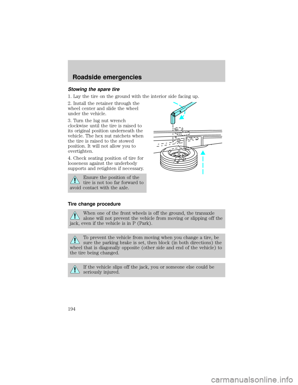
Stowing the spare tire
1. Lay the tire on the ground with the interior side facing up.
2. Install the retainer through the
wheel center and slide the wheel
under the vehicle.
3. Turn the lug nut wrench
clockwise until the tire is raised to
its original position underneath the
vehicle. The hex nut ratchets when
the tire is raised to the stowed
position. It will not allow you to
overtighten.
4. Check seating position of tire for
looseness against the underbody
supports and retighten if necessary.
Ensure the position of the
tire is not too far forward to
avoid contact with the axle.
Tire change procedure
When one of the front wheels is off the ground, the transaxle
alone will not prevent the vehicle from moving or slipping off the
jack, even if the vehicle is in P (Park).
To prevent the vehicle from moving when you change a tire, be
sure the parking brake is set, then block (in both directions) the
wheel that is diagonally opposite (other side and end of the vehicle) to
the tire being changed.
If the vehicle slips off the jack, you or someone else could be
seriously injured.
Roadside emergencies
194
Page 195 of 280
1. Park on a level surface, activate
hazard flashers and set parking
brake.
2. Place gearshift lever in P (Park),
turn engine OFF, and block the
diagonally opposite wheel.
3. Remove the spare tire, jack and
lug wrench.
4. Remove the center ornament or wheel cover from the wheel with the
tapered end of the wheel nut wrench. Insert and twist the handle, then
pry against the wheel.
5. Loosen each wheel lug nut
one-half turn counterclockwise but
do not remove them until the wheel
is raised off the ground.
If Ford Accessory Running Boards
have been installed, use the jack
adapters supplied with the running
boards as described on the inside of
the jack storage area.
6. Locate the jack notch next to the
door closest to the tire you are
changing, then place the jack on the
frame rail directly behind the notch.
Roadside emergencies
195
Page 197 of 280
JUMP STARTING YOUR VEHICLE
The gases around the battery can explode if exposed to flames,
sparks, or lit cigarettes. An explosion could result in injury or
vehicle damage.
Do not push start your vehicle. You could damage the catalytic
converter.
Batteries contain sulfuric acid which can burn skin, eyes, and
clothing, if contacted.
Do not attempt to push start your vehicle. Automatic
transmissions do not have push-start capability.
Preparing your vehicle
1.Use only a 12±volt supply to start your vehicle.
2. Do not disconnect the battery of the disabled vehicle as this could
damage the vehicle's electrical system.
3. Park the booster vehicle close to the hood of the disabled vehicle
making sure the two vehiclesdo nottouch. Set the parking brake on
both vehicles and stay clear of the engine cooling fan and other moving
parts.
4. Check all battery terminals and remove any excessive corrosion before
you attach the battery cables. Ensure that vent caps are tight and level.
5. Turn the heater fan on in both vehicles to protect any electrical
surges. Turn all other accessories off.
Roadside emergencies
197
Page 203 of 280

SERVICE RECOMMENDATIONS
To help you service your vehicle:
²We highlight do-it-yourself items in the engine compartment for easy
location.
²We provide a Scheduled Maintenance Guide which makes tracking
routine service easy.
If your vehicle requires professional service, your dealership can provide
necessary parts and service. Check your ªWarranty Guideº to find out
which parts and services are covered.
Use only recommended fuels, lubricants, fluids and service parts
conforming to specifications. Motorcraft parts are designed and built to
provide the best performance in your vehicle.
PRECAUTIONS WHEN SERVICING YOUR VEHICLE
Be especially careful when inspecting or servicing your vehicle.
²Do not work on a hot engine.
²When the engine is running, make sure that loose clothing, jewelry or
long hair does not get caught up in moving parts.
²Do not work on a vehicle with the engine running in an enclosed
space, unless you are sure you have enough ventilation.
²Keep all lit cigarettes, open flames and other lit material away from
the battery and all fuel related parts.
If you disconnect the battery, the engine must ªrelearnº its idle
conditions before your vehicle will drive properly, as explained inBattery
in this chapter.
Working with the engine off
1. Set the parking brake and ensure the gearshift is securely latched in P
(Park).
2. Turn off the engine and remove the key.
3. Block the wheels to prevent the vehicle from moving unexpectedly.
Working with the engine on
1. Set the parking brake and ensure the gearshift is securely latched in P
(Park).
2. Block the wheels to prevent the vehicle from moving unexpectedly.
Maintenance and care
203