Page 176 of 280

²Service your vehicle more frequently if you tow a trailer. Refer to
Special Operating Conditions in the Scheduled Maintenance Guide.
²Do not tow a trailer until your vehicle has been driven at least 800 km
(500 miles).
²Refer to the instructions included with towing accessories for the
proper installation and adjustment specifications.
If your vehicle is equipped with the optional heavy duty trailer tow
wiring, it is pre-wired for trailer towing. An electrical connector is
provided under the instrument panel for installing a customer-supplied
electric brake controller. Another electrical connector is provided at the
hitch. This connector provides power to the trailer for taillamps, stop
and turn lamps, back up lamps, battery charge, electric brakes (when a
customer provided controller is installed) and ground. The kit included
with your vehicle provides you with adaptors to attach the brake
controller and convert the hitch connector for Class I trailer usage.
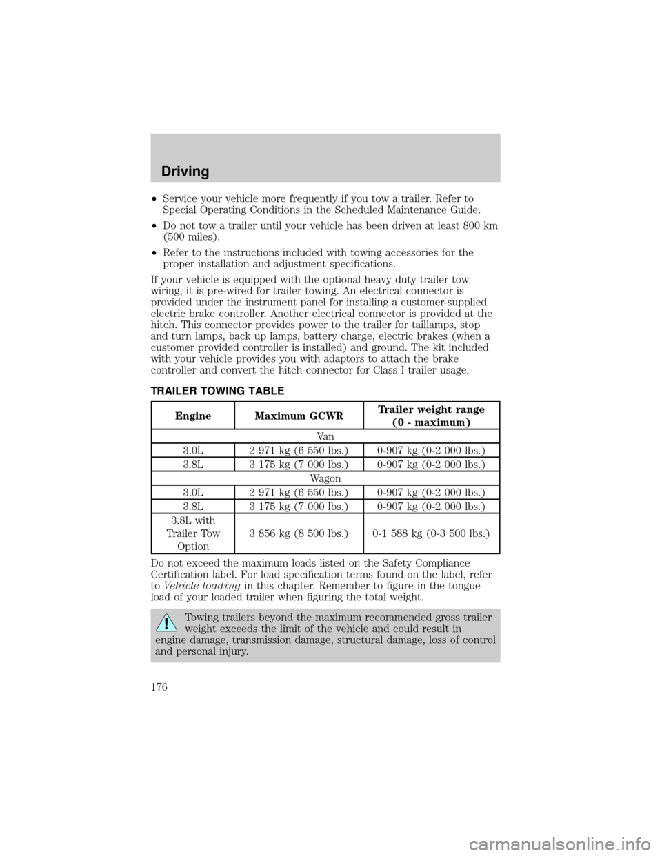
TRAILER TOWING TABLE
Engine Maximum GCWRTrailer weight range
(0 - maximum)
Va n
3.0L 2 971 kg (6 550 lbs.) 0-907 kg (0-2 000 lbs.)
3.8L 3 175 kg (7 000 lbs.) 0-907 kg (0-2 000 lbs.)
Wagon
3.0L 2 971 kg (6 550 lbs.) 0-907 kg (0-2 000 lbs.)
3.8L 3 175 kg (7 000 lbs.) 0-907 kg (0-2 000 lbs.)
3.8L with
Trailer Tow
Option3 856 kg (8 500 lbs.) 0-1 588 kg (0-3 500 lbs.)
Do not exceed the maximum loads listed on the Safety Compliance
Certification label. For load specification terms found on the label, refer
toVehicle loadingin this chapter. Remember to figure in the tongue
load of your loaded trailer when figuring the total weight.
Towing trailers beyond the maximum recommended gross trailer
weight exceeds the limit of the vehicle and could result in
engine damage, transmission damage, structural damage, loss of control
and personal injury.
Driving
176
Page 183 of 280

Always replace a fuse with one that has the specified amperage
rating. Using a fuse with a higher amperage rating can cause
severe wire damage and could start a fire.
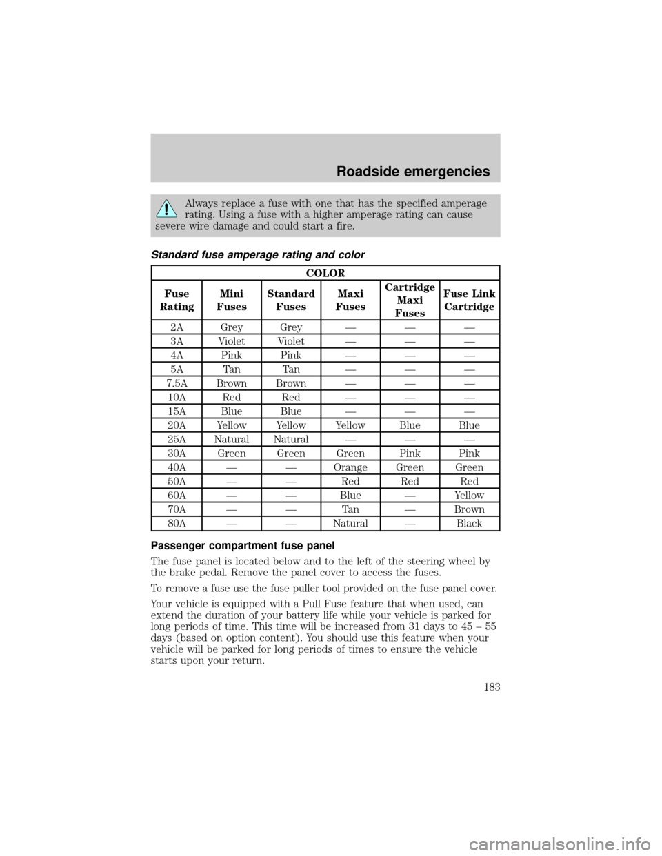
Standard fuse amperage rating and color
COLOR
Fuse
RatingMini
FusesStandard
FusesMaxi
FusesCartridge
Maxi
FusesFuse Link
Cartridge
2A Grey Grey Ð Ð Ð
3A Violet Violet Ð Ð Ð
4A Pink Pink Ð Ð Ð
5A Tan Tan Ð Ð Ð
7.5A Brown Brown Ð Ð Ð
10A Red Red Ð Ð Ð
15A Blue Blue Ð Ð Ð
20A Yellow Yellow Yellow Blue Blue
25A Natural Natural Ð Ð Ð
30A Green Green Green Pink Pink
40A Ð Ð Orange Green Green
50A Ð Ð Red Red Red
60A Ð Ð Blue Ð Yellow
70A Ð Ð Tan Ð Brown
80A Ð Ð Natural Ð Black
Passenger compartment fuse panel
The fuse panel is located below and to the left of the steering wheel by
the brake pedal. Remove the panel cover to access the fuses.
To remove a fuse use the fuse puller tool provided on the fuse panel cover.
Your vehicle is equipped with a Pull Fuse feature that when used, can
extend the duration of your battery life while your vehicle is parked for
long periods of time. This time will be increased from 31 days to 45 ± 55
days (based on option content). You should use this feature when your
vehicle will be parked for long periods of times to ensure the vehicle
starts upon your return.
Roadside emergencies
183
Page 187 of 280

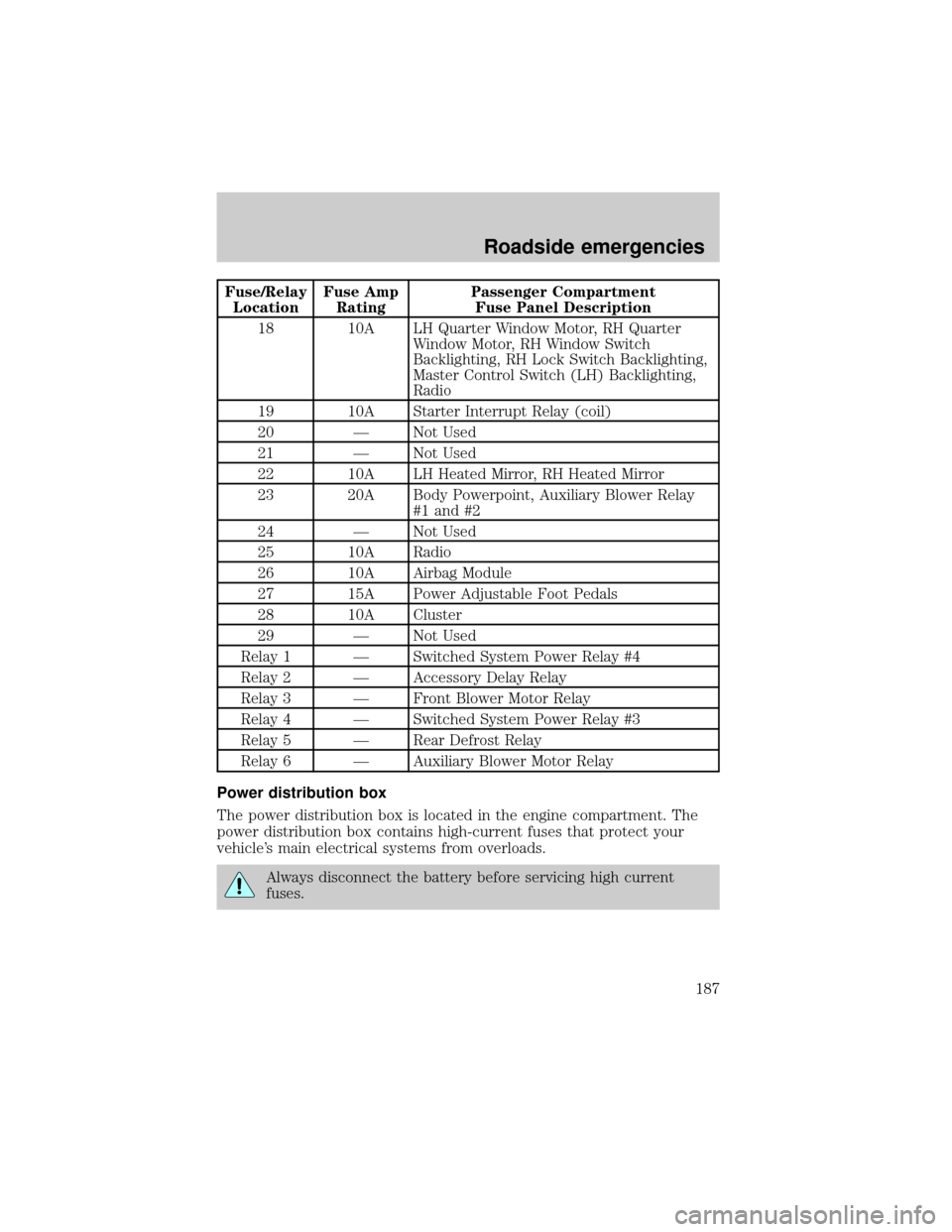
Fuse/Relay
LocationFuse Amp
RatingPassenger Compartment
Fuse Panel Description
18 10A LH Quarter Window Motor, RH Quarter
Window Motor, RH Window Switch
Backlighting, RH Lock Switch Backlighting,
Master Control Switch (LH) Backlighting,
Radio
19 10A Starter Interrupt Relay (coil)
20 Ð Not Used
21 Ð Not Used
22 10A LH Heated Mirror, RH Heated Mirror
23 20A Body Powerpoint, Auxiliary Blower Relay
#1 and #2
24 Ð Not Used
25 10A Radio
26 10A Airbag Module
27 15A Power Adjustable Foot Pedals
28 10A Cluster
29 Ð Not Used
Relay 1 Ð Switched System Power Relay #4
Relay 2 Ð Accessory Delay Relay
Relay 3 Ð Front Blower Motor Relay
Relay 4 Ð Switched System Power Relay #3
Relay 5 Ð Rear Defrost Relay
Relay 6 Ð Auxiliary Blower Motor Relay
Power distribution box
The power distribution box is located in the engine compartment. The
power distribution box contains high-current fuses that protect your
vehicle's main electrical systems from overloads.
Always disconnect the battery before servicing high current
fuses.
Roadside emergencies
187
Page 188 of 280
Always replace the cover to the Power Distribution Box before
reconnecting the battery or refilling fluid reservoirs.
If the battery has been disconnected and reconnected, refer to the
Batterysection of theMaintenance and carechapter.
The high-current fuses are coded as follows:
Fuse/Relay
LocationFuse Amp
RatingPower Distribution Box Description
1 30A* Powertrain Control Module Relay
2 10A* Powertrain Control Module, Front
Electronic Module
3 10A* A/C Compressor Clutch
4 25A* Horns, Horn Relay (coil)
5 15A* Fuel Pump Motor, Powertrain Control
Module
6 30A* Front Wiper Motor, Front Wiper Relay,
Front Washer Pump, FEM
7 25A* Rear Wiper Motor, Rear Washer Pump, Rear
Wiper Relay (coil)
8 Ð Not Used
9 15A* Right Headlamp (Low and High Beam)
503
304
303
302301
502
501
207201
202
203
204122118114110106102
121117113109105101
120116112108104
119115111107103
24
209206
208
18161412108642
1715131197531
205
23
22
21
401
20
19
Roadside emergencies
188
Page 197 of 280

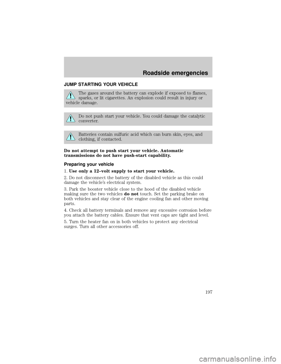
JUMP STARTING YOUR VEHICLE
The gases around the battery can explode if exposed to flames,
sparks, or lit cigarettes. An explosion could result in injury or
vehicle damage.
Do not push start your vehicle. You could damage the catalytic
converter.
Batteries contain sulfuric acid which can burn skin, eyes, and
clothing, if contacted.
Do not attempt to push start your vehicle. Automatic
transmissions do not have push-start capability.
Preparing your vehicle
1.Use only a 12±volt supply to start your vehicle.
2. Do not disconnect the battery of the disabled vehicle as this could
damage the vehicle's electrical system.
3. Park the booster vehicle close to the hood of the disabled vehicle
making sure the two vehiclesdo nottouch. Set the parking brake on
both vehicles and stay clear of the engine cooling fan and other moving
parts.
4. Check all battery terminals and remove any excessive corrosion before
you attach the battery cables. Ensure that vent caps are tight and level.
5. Turn the heater fan on in both vehicles to protect any electrical
surges. Turn all other accessories off.
Roadside emergencies
197
Page 198 of 280
Connecting the jumper cables
1. Connect the positive (+) booster cable to the positive (+) terminal of
the discharged battery.
Note:In the illustrations,lightning boltsare used to designate the
assisting (boosting) battery.
2. Connect the other end of the positive (+) cable to the positive (+)
terminal of the assisting battery.
+–+–
+–+–
Roadside emergencies
198
Page 199 of 280
3. Connect the negative (-) cable to the negative (-) terminal of the
assisting battery.
4. Make the final connection of the negative (-) cable to an exposed
metal part of the stalled vehicle's engine, away from the battery and the
carburetor/fuel injection system.Do notuse fuel lines, engine rocker
covers or the intake manifold asgroundingpoints.
Do not connect the end of the second cable to the negative (-)
terminal of the battery to be jumped. A spark may cause an
explosion of the gases that surround the battery.
5. Ensure that the cables are clear of fan blades, belts, moving parts of
both engines, or any fuel delivery system parts.
+–+–
+–+–
Roadside emergencies
199
Page 200 of 280
Jump starting
1. Start the engine of the booster vehicle and run the engine at
moderately increased speed.
2. Start the engine of the disabled vehicle.
3. Once the disabled vehicle has been started, run both engines for an
additional three minutes before disconnecting the jumper cables.
Removing the jumper cables
Remove the jumper cables in the reverse order that they were
connected.
1. Remove the jumper cable from thegroundmetal surface.
2. Remove the jumper cable on the negative (-) connection of the
booster vehicle's battery.
+–+–
+–+–
Roadside emergencies
200