Page 6 of 232
A
ONOFF
+ –
0 12204060
80
100
1202060
140
180
P R N D 2 1MPH km/h
000000
0000
EFC H
FUEL DOOR >
THEFT LOW
COOLANT
Parking brake
release
(pg. 115) Headlamp
control
(pg. 16)Panel dimmer
(pg. 17)
Driver air bag
(pg. 94) Trunk release Ð
sedan only
(pg. 57)
Rear window wiper and
washer Ð wagon only*
(pg. 48)
Turn signal and
wiper/washer control
(pg. 47)Instrument cluster
(pg. 8)
* if equipped
Instrumentation
6
Page 8 of 232
WARNING LIGHTS AND CHIMES
Turn signal
Illuminates when the left or right
turn signal or the hazard lights are
turned on. If one or both of the
indicators stay on continuously or
flash faster, check for a burned-out
turn signal bulb. Refer toExterior bulbsin theMaintenance and care
chapter.
High beams
Illuminates when the high beam
headlamps are turned on.
Traction ControlYactive (if equipped)
Momentarily illuminates when the
ignition is turned to ON. It also
illuminates when the Traction
Controlysystem begins applying
and releasing the brakes and
adjusting the engine characteristics to limit a wheelspin condition. It will
be lit for the duration of the Traction Controlyevent.
For more information, refer to theDrivingchapter.
P!
BRAKE
+ –
CRUISE
RPMx1000
ABS0 123
4
5
6
7
204060
80
100
1202060
140
180
P R N D D 1MPH km/h
000000
0000
EFC H
FUEL DOOR >
THEFTLOW
COOLANT
Instrumentation
8
Page 42 of 232

Radio frequency information
The Federal Communications Commission (FCC) and the Canadian Radio
and Telecommunications Commission(CRTC) establish the frequencies
AM and FM stations may use for their broadcasts. Allowable frequencies
are:
AM 530, 540±1600, 1610 kHz
FM 87.7, 87.9±107.7, 107.9 MHz
Not all frequencies are used in a given area.
Radio reception factors
Three factors can affect radio reception:
²Distance/strength.The further an FM signal travels, the weaker it is.
The listenable range of the average FM station is approximately 40 km
(24 miles). This range can be affected by ªsignal modulation.º Signal
modulation is a process radio stations use to increase their
strength/volume relative to other stations.
²Terrain.Hills, mountains and tall buildings between your vehicle's
antenna and the radio station signal can cause FM reception problems.
Static can be caused on AM stations by power lines, electric fences,
traffic lights and thunderstorms. Moving away from an interfering
structure (out of its ªshadowº) returns your reception to normal.
²Station overload.Weak signals are sometimes captured by stronger
signals when you pass a broadcast tower. A stronger signal may
temporarily overtake a weaker signal and play while the weak station
frequency is displayed.
The audio system automatically switches to single channel reception if it
will improve the reception of a station normally received in stereo.
Audio system warranties and service
Refer to the ªWarranty Guideº for audio system warranty information.
If service is necessary, see your dealer or a qualified technician.
Controls and features
42
Page 47 of 232
TURN SIGNAL CONTROL
²Push down to activate the left
turn signal.
²Push up to activate the right turn
signal.
WINDSHIELD WIPER/WASHER CONTROLS
Rotate the windshield wiper control
to the desired interval, low or high
speed position.
The bars of varying length are for
intermittent wipers. When in this
position rotate the control upward
for fast intervals and downward for
slow intervals.
Push the control on the end of the
stalk to activate washer. Push and
hold for a longer wash cycle. The
washer will automatically shut off
after ten seconds of continuous use.
Mist Function
To operate the Mist function of the
windshield wipers, push and release
the windshield washer control
quickly. The wipers will cycle one or
two times.
Controls and features
47
Page 135 of 232

Fuse/Relay
LocationFuse Amp
RatingPassenger Compartment
Fuse Panel Description
13 20A Cigar Lighter, Auxiliary Power Point
14 Ð Not Used
15 30A Front Wiper Motor
16 15A Flasher and GEM Power, Integrated Control
Panel (ICP) Power, RCC Memory, Cluster
17 15A Stop Lamp, Speed Control Deactivating
Switch
18 Ð Not Used
19 Ð Not Used
20 Ð Not Used
21 Ð Not Used
22 20A Deck Lid Release Solenoid, Lock/Unlock
Relays
23 10A Air Bag Module, PATS Transceiver
24 15A Transit Relay
25 2A PCM Relay
26 10A Mirrors, Power Antenna, Pulse Stretcher
Module, Deck Lid Lamp, Battery Saver
27 10A Gauges and Warning Lamps, Integrated
Control Panel (ICP), FFV Sender, GEM
28 10A Blower Motor Relay Coil, EATC Logic
29 15A Autolamps, Headlamp Switch
30 15A Horns and Horn Switch, OBD II Connector
31 Ð Not Used
32 10A ABS, DRL Relay Coil, Speed Control
Actuator, Traction Control Switch, AC
Heater Selector Switch, Blend Door
Actuator, Brake Shift Interlock
33 Ð Not Used
34 Ð Not Used
35 Ð Not Used
36 15A Turn Signals, Back-up Lamps
Roadside emergencies
135
Page 189 of 232

permitted to intentionally remove an emission control device or prevent
it from working. Information about your vehicle's emission system is on
the Vehicle Emission Control Information Decal located on or near the
engine. This decal identifies engine displacement and gives some tune up
specifications.
Please consult your ªWarranty Guideº for complete emission warranty
information.
Readiness for Inspection/Maintenance (I/M) testing
In some localities, it may be a legal requirement to pass an I/M test of
the on-board diagnostics system. If your
indicator is on, refer to the
description in theWarning Lights and Chimessection of the
Instrumentationchapter. Your vehicle may not pass the I/M test with
the
indicator on.
If the vehicle's powertrain system or its battery has just been serviced,
the on-board diagnostics system is reset to a ªnot ready for I/M testº
condition. To ready the on-board diagnostics system for I/M testing, a
minimum of 30 minutes of city and highway driving is necessary as
described below:
²First, at least 10 minutes of driving on an expressway or highway.
²Next, at least 20 minutes driving in stop-and-go, city-type traffic with
at least four idle periods.
Allow the vehicle to sit for at least eight hours without starting the
engine. Then, start the engine and complete the above driving cycle. The
engine must warm up to its normal operating temperature. Once started,
do not turn off the engine until the above driving cycle is complete.
BULBS
Replacing exterior bulbs
Check the operation of the following lamps frequently:
²Headlamps
²Tail lamps
²Brakelamps
²High-mount brakelamp
²Turn signals
²Backup lamps
Maintenance and care
189
Page 192 of 232

2. Install the bulb retaining ring over the plastic base and lock the ring
by rotating clockwise until it snaps into place.
3. Connect the electrical connector to the bulb.
4. Install the protective dust shield and lock the shield by rotating it
clockwise until it locks into position.
5. Carefully position the headlamp assembly onto the vehicle.
6. Hold the headlamp assembly snugly against the vehicle and install the
retainer pins straight down to lock the lamp into place.
7. Before reinstalling the bolt, make sure the retainer pins are fully
seated, and install bolt on headlamp housing.
8. Turn the headlamps on and make sure they work properly. If the
headlamp was correctly aligned before you changed the bulb, you should
not need to align it again.
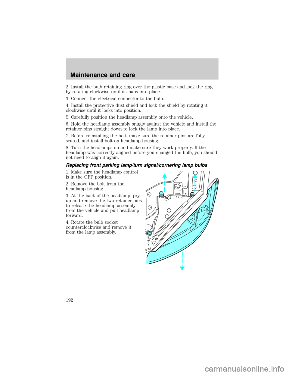
Replacing front parking lamp/turn signal/cornering lamp bulbs
1. Make sure the headlamp control
is in the OFF position.
2. Remove the bolt from the
headlamp housing.
3. At the back of the headlamp, pry
up and remove the two retainer pins
to release the headlamp assembly
from the vehicle and pull headlamp
forward.
4. Rotate the bulb socket
counterclockwise and remove it
from the lamp assembly.
Maintenance and care
192
Page 194 of 232
1. Remove screw and the license
plate lamp assembly from liftgate.
2. Remove bulb socket by turning
counterclockwise.
3. Carefully pull the bulb out from
the socket and push in the new
bulb.
4. Install the lamp assembly on
liftgate with screw.
Replacing tail/brake/turn signal/backup lamp bulbs
Sedan
The tail lamp, brake lamp, turn
signal lamp and backup lamp bulbs
are located in the same portion of
the tail lamp assembly. Follow the
same steps to replace either bulb.
1. Open trunk and remove two
plastic mushroom nuts, five push
pins and the plastic cover from
inside the trunk to access the lamp
assembly.
2. Carefully pull the carpet away to
expose the lamp assembly hardware.
3. Remove three nut and washer
assemblies and the lamp assembly
from the vehicle.
Maintenance and care
194