2000 FORD F750 wheel torque
[x] Cancel search: wheel torquePage 92 of 208

Block the wheels to prevent the vehicle from moving.
Unexpected and possibly sudden vehicle movement may occur if
these precautions are not taken.
Impact wrenches should not be used as they may damage the piston and
prevent proper caging of the spring. Do not apply more than 68 Nm (50
lb-ft) torque to the release bolt nut.
1. Remove the stud tool and nut
from the carrying pocket on the
brake chamber assembly.
2. Remove the access plug from the
end of the spring chamber.
3. Insert the release stud through
the opening in the chamber and into
the spring pressure plate.
4. Turn the release stud one-quarter
turn to engage the stud tangs with
the slot in the pressure plate. Keep
the stud engaged and install the nut
on the release stud.
5. Tighten the nut until the spring is
fully caged and the brakes are
released. Do not loosen or remove
the release stud and nut unless the brake chamber is completely
assembled and is securely clamped.
6. When the air pressure is restored, unscrew and remove the release
stud and install in the carrying pocket. Install the access plug.
Driving
92
Page 102 of 208

When operating the PTO unit with the vehicle stationary, first set the
parking brake (chock the wheels if the vehicle is on a hill or other
unlevel surface).
DRIVING WITH AN AUTOMATIC TRANSMISSION, IF EQUIPPED
Allison automatic transmission
Do not allow your vehicle to coast in N (Neutral). Transmission
braking is not available in N (Neutral). Allowing the vehicle to
coast in N (Neutral) could result in loss of vehicle control and severe
transmission damage.
The Allison automatic transmissions are a torque converter type, full
power shifting and fully automatic. They also have the added flexibility
of manually selecting and holding in the lower drive ranges which permit
the drive selection of the most suitable gear range to match varying road
and load conditions. To prevent destructive overspeeding of the engine,
the hold feature is not infinite, resulting in upshifts from the hold range
to the next higher range at some speed above the no-load governed
speed of the engine.
Allison AT-545
These transmissions have no P (Park) position. Before leaving
the driver’s seat, always shift into N (Neutral) and set the
parking brake. Shut off the engine and remove your ignition key.
Always use wheel chocks for hilly or off-road parking. Unexpected and
possibly sudden vehicle movement may occur if these precautions are
not taken.
This transmission provides four forward speeds and one reverse range.
R (Reverse)
Use this position to back the vehicle. Completely stop the vehicle before
shifting from R (Reverse) to any forward gear (1, 2, 3 or D). The reverse
warning signal will sound when the selector is in R (Reverse). Reverse
has only one gear and provides the greatest gear reduction.
Driving
102
Page 111 of 208

The PTO gear is in constant mesh with the drive gear in the torque
converter housing. A friction clutch or constant drive is used to transmit
power to the PTO.
Power take-off (PTO) operation on vehicles equipped with a
Caterpillar 3126E engine
If your vehicle is equipped with a Caterpillar 3126E engine, the PTO will
only operate if the vehicle is in Neutral. This feature can be overriden by
a special service tool; see your dealer or service representative for more
information.
MAXIMUM VEHICLE LOADING
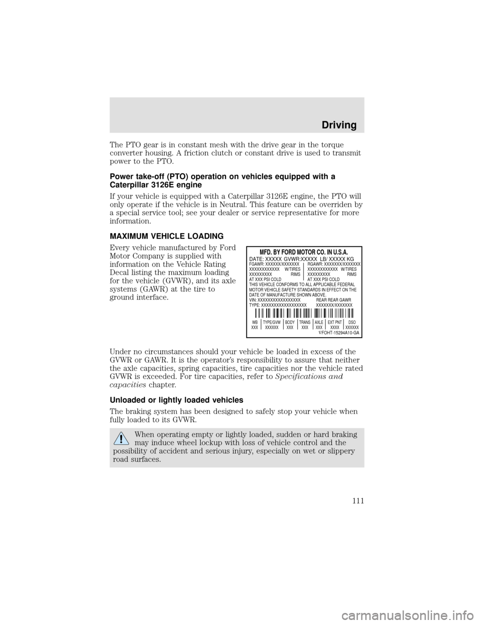
Every vehicle manufactured by Ford
Motor Company is supplied with
information on the Vehicle Rating
Decal listing the maximum loading
for the vehicle (GVWR), and its axle
systems (GAWR) at the tire to
ground interface.
Under no circumstances should your vehicle be loaded in excess of the
GVWR or GAWR. It is the operator’s responsibility to assure that neither
the axle capacities, spring capacities, tire capacities nor the vehicle rated
GVWR is exceeded. For tire capacities, refer toSpecifications and
capacitieschapter.
Unloaded or lightly loaded vehicles
The braking system has been designed to safely stop your vehicle when
fully loaded to its GVWR.
When operating empty or lightly loaded, sudden or hard braking
may induce wheel lockup with loss of vehicle control and the
possibility of accident and serious injury, especially on wet or slippery
road surfaces.
MFD. BY FORD MOTOR CO. IN U.S.A.
WB TYPE/GVW BODY TRANS AXLE EXT PNT DSO
XXX XXXXXX XXX XXX XXX XXXX XXXXXX
∇FOHT-15294A10-GA
DATE: XXXXX GVWR:XXXXX LB/ XXXXX KGFGAWR: XXXXXX/XXXXXXX RGAWR: XXXXXXX/XXXXXXX
XXXXXXXXXXXX W/TIRES XXXXXXXXXXXX W/TIRES
XXXXXXXXX RIMS XXXXXXXXX RIMS
AT XXX PSI COLD AT XXX PSI COLD
THIS VEHICLE CONFORMS TO ALL APPLICABLE FEDERAL
MOTOR VEHICLE SAFETY STANDARDS IN EFFECT ON THE
DATE OF MANUFACTURE SHOWN ABOVE.
VIN: XXXXXXXXXXXXXXXXX REAR REAR GAWR
TYPE: XXXXXXXXXXXXXXXXXX XXXXXXX/XXXXXXX
Driving
111
Page 147 of 208

SERVICING YOUR WHEELS AND TIRES
Wheel assembly
Your vehicle is fitted with hub
piloted wheels and two-element
swiveling lug nuts (20 & 22 mm).
Do not use taper type wheels or ball
seat wheel nuts.
•Do not paint the mating face of the hub/drum.
•Do not paint the two-element swiveling lug nuts or wheel stud.
•Do not allow an excessive thickness of paint to build between the disc
wheel mounting surfaces.
•Do not install disc wheels where the paint has not fully cured.
•At wheel changes, ensure mounting faces are clean and free of rust,
dirt and excess paint.
If fasteners are needed, use only Ford recommended replacement parts.
•To maintain the desired
torque/tension relation between
nut body and flange, it is
necessary to use clean engine oil
meeting Ford specification
WSS-M2C153-G between nut body and flange. Lubricate the nut body
and flange any time a wheel is removed.
The M20 & M22 wheel nuts are right-hand threads. Refer to the
following chart for approved wheel lug nut torque.
Wheel type Bolt size Wheel nut torque
10-hole disc
285.75 mm bolt circleM22 (22 by 1.5 mm) 610-677 Nm
(450-500 lb-ft)
8-hole disc
19.5x6.75 mm bolt circleM20 (20 by 1.5 mm) 610-677 Nm
(450-500 lb-ft)
The disc wheel nuts on your vehicle were tightened before delivery.
Recheck torque of nuts at 160 km (100 miles) and 800 km (500 miles) of
new vehicle operation or any time a wheel is removed. Reset to
recommended torque levels.
Maintenance and care
147
Page 150 of 208

Tire inflation pressure must not exceed the recommendations of
the axle, tire and/or wheel rim manufacturer for the specific
load, speed and application. The inflation pressures on the tire sidewall
do not take the wheel rim capabilities into consideration.
Never use a rim of different manufacture or any different size or
type than original rims.
Try to replace tires in pairs on the same axle shaft. Tires larger or
smaller than originally installed may affect the accuracy of the
speedometer. Consult your dealer about the need to change the switch
setting on the back of the speedometer.
Front wheel alignment
If abnormal tire wear or ride and handling characteristics such as vehicle
lead or wander are experienced with properly inflated tires, the front
end alignment should be checked.
Wheel bearing care
Front and rear wheel bearings are adjustable to correct for bearing and
spindle wear. Long bearing life depends upon proper adjustment and
correct lubrication. If bearings are adjusted too tightly (preloaded) they
will overheat and wear rapidly. Loose adjustment will cause pounding
and will contribute to uneven tire wear, steering difficulties and
inefficient brake operation.
Refer to the Ford Service Manual applicable to your vehicle for proper
tightening procedures and torque specifications.
Periodically check the oil level on oil filled front bearing hubs. If
necessary, add oil through the filler plug so the oil level is between the
ADD and FULL marks indicated on the hub. Do not overfill. Overfilling
can result in oil on brake linings.
Refer to your Scheduled Maintenance Guide for fluid level checks and
change intervals for the front hubs.
Your front hubs may be filled with an optional synthetic fluid which
allows use of the extended service intervals. A blue colored filler plug
identifies use of the synthetic fluid.
Maintenance and care
150
Page 189 of 208

Maintenance Operation Frequency - Observation
Check the transmission and
engine mountings (*b)Hard shifting or excessive vibration
Check and adjust transmission
controls (*b)High effort to shift or noisy
transmission
Check fuel pump pressure Insufficient full-throttle power or
backfiring
Clean radiator cap seal. Clean
and inspect the cap surface on
the radiatorWhen the cap does not hold pressure
Check the battery terminals for
corrosionWhenever electrical power supply has
diminished
Tighten the wheel mounting
nuts to the specified torque.
Refer toServicing your
wheels and tiresRequired initially at 804 and 1 609 km
(500 and 1 000 miles). Perform again
at 804 and 1 609 km (500 and 1 000
mile) intervals after each tire
removal/replacement.
*a During maintenance and repair, protect the fuel tube and the hose
assemblies, the power steering lines, and the air brake lines from the
external heat, the acids and the abrasion that could damage the lines.
*b Check for (free) linkage action and ensure that (return) spring
force is adequate to maintain pedal free play.
*c Adjust, repair or replace as required with the same or equivalent
parts.
General maintenance information
189