2000 FIAT MAREA brake fluid
[x] Cancel search: brake fluidPage 16 of 330

Marea-Marea Weekend
2000 range (§)
Introduction
Product characteristics FL Group
OO.o
Name of
product
Description
International designation Application
SELENIA 20K
Synthetic SAE 10W40 multigrade engine oil.
Exceeds specifications ACEA A3-96/CCMC G5 and API
SJ
SELENIA
PERFORMER
Synthetic SAE 5W-30 multigrade engine oil. Exceeds
specifications ACEA A1 and API SJ
Temperatures below
- 20°C
SELENIA
Turbo Diesel
Synthetic SAE 10W40 multigrade engine oil
Exceeds specifications ACEA B3 and API CD
SELENIA
WR DIESEL
Synthetic SAE 5W-40 multigrade engine oil. Exceeds
specifications ACEA B3 and API CF
Temperatures below
- 15°C
TUTELA CAR
ZC 75 SYNTH
SAE 75W-80 EP oil. Satisfies standards MIL-L-2105 D
LEV and API GL 5
Manual gearboxes and
differentials
TUTELA Gl/A «ATF DEXR0N II D LEV» SAE 10W type oil for hydraulic
power assisted steering
Hydraulic power as
sisted steering
TUTELA GI/2 « ATF DEXRON II D LEV» SAE 10W type oil for auto
matic transmissions
Automatic
gearboxes
TUTELA MRM2 Water repellant, lithium soap based grease containing
molybdenum disulphide, consistency NLGI = 2 Constant velocity joints
TUTELA TOP 4 Synthetic fluid NHTSA n° 116 D0T4, ISO 4925, SAE
J-1703 and CUNA NC 956-01
Hydraulic brakes and
hydraulically operated
clutches
DP1 Mixture of alcohol, water and surface active agents
CUNA NC 956-11
To be used undiluted
or diluted in windscreen
washer systems
Paraflu11
Anti-freeze for cooling systems with mono-ethylene gly
col base
CUNA NC 956-16
Cooling circuits
Percentage to be used
50% up to -35°C
Diesel Mix Additive for diesel fuel with protective action for Die
sel engines
To be mixed with die
sel fuel (25 cc per 10
litres)
Copyright by Fiat Auto 9
Page 144 of 330

Electrical equipment
Instrument panel
Marea-Marea Weekend
2000 range ©
55.
INSTRUMENT PANEL (excluding C.A.)
3 4 56789 10 11 12
21 20 1918 17 24 16 15 14 13 23 22
Front side
1. Fuel level gauge
2. Fuel reserve warning light
3. Speedometer
4. ABS failure warning light
5. Brake pad wear warning light
6. Left direction indicator warning light
7. Side lights warning light
8. Right direction indicator warning light
9. Main beam warning light
10. Low brake fluid level and handbrake ap-
plied/EBD system failure warning light
11. Rev counter
12. Engine coolant temperature gauge
13. Air Bag fault warning light
14. Brake light failure warning light
15. Doors open warning ilght
16. Trip counter/mileometer/outdoor tempera
ture gauge
17. Low engine oil pressure warning light
18. Generator warning light
19 Injection system failure warning light
20. FIAT CODE system warning light
21. Heater plugs warning light
22. Seat belt warning light
23. Water in diesel filter warning light
24. EOBD warning light
14 Print rf 506.763/23
Page 145 of 330

Marea- Marea Weekend
2000 range ©
Electrical equipment
Control module
55.
Wiring diagram
.mrmmmL 18 3 4 5 6 7 8 9 10 U 1213 1415161718 |TTTTrTrrrrTTTTT1.TTTTT1pmL 18 3 4 5 6 7 8 9 10 11 121314151617181920213223248586
n ti
O Mill
(*) JTD
A. Battery recharging warning light
B. Low engine oil pressure warning light
C. Left direction indicator warning light
D. Right direction indicator warning light
E. Side lights warning light
F. Instrument panel symbol lighting
G. Main beam warning light
H. Air Bag fault warning light
I. ABS failure warning light
J. Fuel reserve warning light
K. Fuel level gauge
L. FIAT CODE system warning light
M. Injection system failure warning light
M1. EOBD warning light
N. Water in diesel filter warning light
O. Heater plugs warning light
(**) TD 75 BHP
P. Seat belt warning light
Q. Brake pad wear warning light
R. Low brake fluid/handbrake on/EBD sys
tem failure warning light
S. Brake light electronic control module
T. Brake light failure warning light
U. Doors open warning ilght
V. Speedometer
W. Rev counter
X. Engine coolant temperature gauge
Y. Electronic module
Z. Milometer - trip meter/outside tempera
ture gauge
Z1 Odometer reset button
* Short-circuit plugs
Copyright by Fiat Auto 15
Page 146 of 330

Electrical equipment
Instrument panel
Marea- Marea Weekend
2000 range ©
55.
Rear side (the connector sockets are shown)
Connector A (on front lead) Connector B (on facia lead)
Pin no. Cable colour Circuit involved
1 BV EBD system failure
2 BN Brake fluid level
3 BR Brake pad wear
4 CL Heater plugs (JTD)
5 MN FIAT CODE
6 LN Injection system failure (JTD)
7 HN Battery recharging
8 HG Engine oil minimum pressure
9 LN EOBD (petrol only)
10 RV ABS fault
11 GN Reserve signal (petrol only)
12 VB Speedometer signal
13 AG +30 battery
14 CN Speedometer generator power supply
15 HB engine coolant temperature
16 HL Outdoor temperature signal
17S HM Speedometer signal
18 L Rev counter signal
(*) not connected in this version
Pin no. Cable colour Circuit involved
1 RG Left brake light failure
2 RV Brake light switch
3 RV Brake light switch
4 C Air Bag system fault
5 GV Water in diesel filter (JTD)
6 M Seat belt
7 -N.C.
8 A Left turn signal
9 AN Right turn signal
10 -N.C.
11 GN Side lights
12 LB Main beam headlamps
13 BN Handbrake on
14 RN Right brake light failure
15 H Doors open
16 CN Boot open
17S -N.C.
18 GR Instrument panel light
19 N Lighting earth
20 HG Fuel level
21 GL Outdoor temperature display
22 R +15 from ignition
23 N electronic earth
24 -speedometer signal (*)
25 VN Speedometer signal
26 -speedometer signal (*)
16 Print n° 506.763/23
Page 148 of 330

Electrical equipment
Control module
Marea- Marea Weekend
2000 range ©
55.
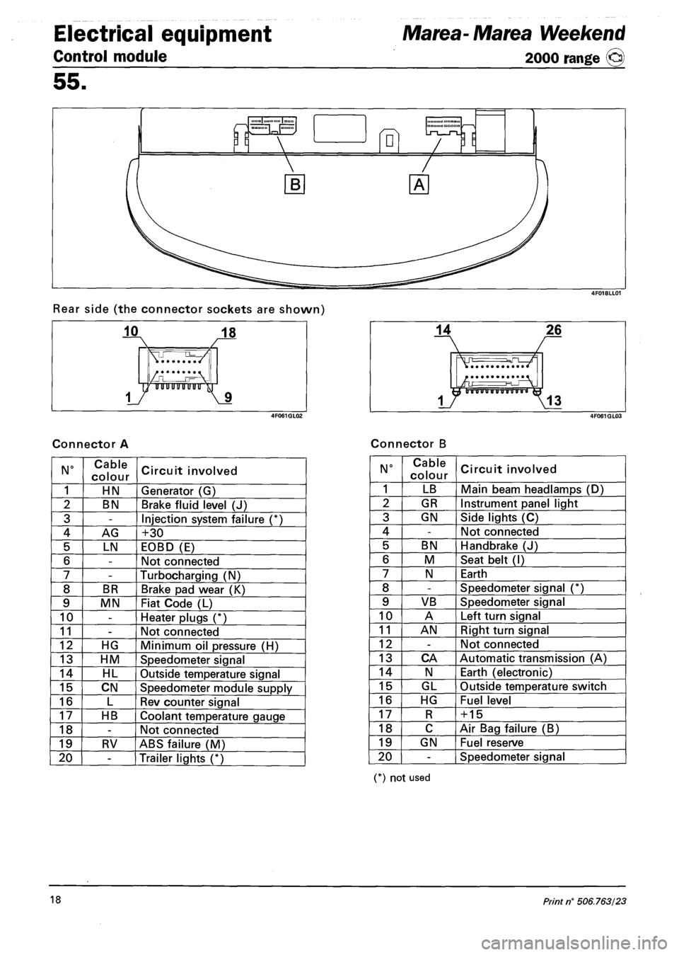
Rear side (the connector sockets are shown)
Connector A Connector B
N° Cable
colour Circuit involved
1 HN Generator (G)
2 BN Brake fluid level (J)
3 -Injection system failure (*)
4 AG +30
5 LN EOBD (E)
6 -Not connected
7 -Turbocharging (N)
8 BR Brake pad wear (K)
9 MN Fiat Code (L)
10 -Heater plugs (*)
11 -Not connected
12 HG Minimum oil pressure (H)
13 HM Speedometer signal
14 HL Outside temperature signal
15 CN Speedometer module supply
16 L Rev counter signal
17 HB Coolant temperature gauge
18 -Not connected
19 RV ABS failure (M)
20 -Trailer lights (*)
N° Cable
colour Circuit involved
1 LB Main beam headlamps (D)
2 GR Instrument panel light
3 GN Side lights (C)
4 -Not connected
5 BN Handbrake (J)
6 M Seat belt (I)
7 N Earth
8 -Speedometer signal (*)
9 VB Speedometer signal
10 A Left turn signal
11 AN Right turn signal
12 -Not connected
13 CA Automatic transmission (A)
14 N Earth (electronic)
15 GL Outside temperature switch
16 HG Fuel level
17 R + 15
18 C Air Bag failure (B)
19 GN Fuel reserve
20 -Speedometer signal
(*) not used
18 Print n° 506.763/23
Page 187 of 330

Marea- Marea Weekend
2000 range ©
Electrical equipment
Wiring diagrams
55.
Electrical symbols
M
Lt3
Position
Main beams
Heated seat
Seat belts
Heated rear windscreen
Handbrake applied and
low brake fluid level
ABS
Hazard warning lights
Direction indicator
Handbrake applied and
low brake fluid level
Recharging
Engine oil pressure
IX!
(O)
Hum®
120 Km/h
Choke
Water in fuel filter
Heater plugs warning
light
Turbocharger pressure
Rear fog lamps
Fog light
Brake pad wear
Turbocharger pressure
Automatic transmission
fluid temperature
Speed limits
Fuel level
Engine coolant
temperature
to
Switch discharge
Dipped beams
Central locking direction
indicators signal
Horns
Left direction indicator
Right direction indicator
Engine cooling
Windscreen wiper
Electronic sun-roof
Catalytic converter
temperature
Resistance
Diode
Copyright by Fiat Auto 1
Page 188 of 330

Electrical equipment
Wiring diagrams
Marea- Marea Weekend
2000 range ©
55.
Electrical symbols
Warning light
Bulb
/--txi
T
Fuse
Switch open
Selector switch
Coil control switch
(relay)
Engine
Rear wiper
Headlamp washer
Windscreen wash/wipe
Rear wash/wipe
Engine oil pressure
BRAKE
SPORT
K
ANT I LOCK
STOP
Trip computer control
Electronic injection
Engine oil level
Brake fluid level
(Japanese, Version)
Doors ajar
Central locking
Controlled damping
suspension Sport
Function
Transistor
Air-bag
ABS (Japanese version)
Car brake failure
Windscreen wiper
H Differential lock
Automatic transmission
fluid temperature
00' Temperature
Antitheft device
Electrically operated
windows
Earth
Number plate lights
Pulse generator (timed
operation)
Analogue clock
Digital clock
Speedometer
Rev counter
2 Print n° 506.763/23
Page 234 of 330

Electrical system
Component location
Marea-Marea Weekend
2000 range ©
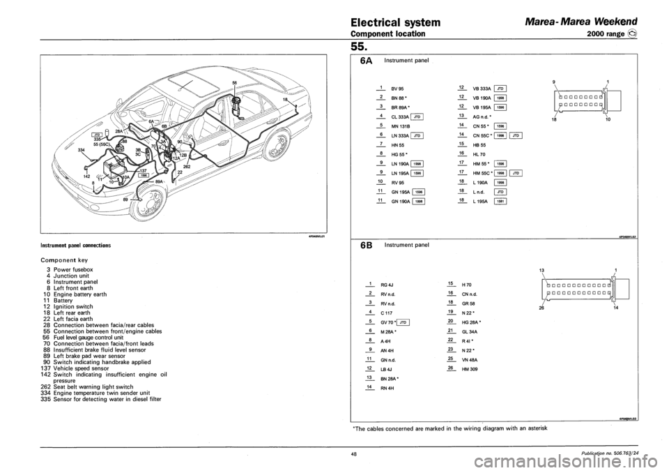
INSTRUMENT PANEL CONNECTIONS
Component key
3
4
6
8
10
11
12
18
22
28
55
56
70
88
89
90
Power fusebox
Junction unit
Instrument panel
Left front earth
Engine battery earth
Battery
Ignition switch
Left rear earth
Left facia earth
Connection between facia/rear cables
Connection between front/engine cables
Fuel level gauge control unit
Connection between facia/front leads
Insufficient brake fluid level sensor
Left brake pad wear sensor
Switch indicating handbrake applied
137 Vehicle speed sensor
142 Switch indicating insufficient engine oil
pressure
262 Seat belt warning light switch
334 Engine temperature twin sender unit
335 Sensor for detecting water in diesel filter
55.
Instrument panel
1
2
3
4
5
6
7
8
9
9
10
11
11
F3V95
BN 88*
BR 89A*
CL 333A I JTD
MN 131B
LN 333A | JTD
HN55
HG55*
LN 190A 1998
LN 195A | 1596
RV95
GN 195A 1596
GN 190A 1998
12
12
12
13
14
14
15
16
17
17
18
18
18
VB 333A JTD
VB 190A 1998
1596
1998
VB 195A | 1596
AG n.d. *
CN 55 *
CN 55C *
HB 55
HL70
HM 55*
HM 55C * |
L190A
Ln.d.
L195A
•••••••
•••••••
18 10
JTD
1596
1998
1998
JTD
1581
6B Instrument panel
13
1
2
3
4
5
6
8
9
11
12
13
14
RG4J
RV n.d.
RV n.d.
C117
GV 70 *| JTD
M28A*
A4H
AN4H
GN n.d.
LB4J
BN 28A *
RN 4H
15
16
18
19
20
21
22
23
25
26
H70
CN n.d.
GR 58
N22*
HG 28A *
GL34A
R4I *
N22*
VN48A
HM309
•••••••••••
•••••••••••
26 14
4F048ML03
The cables concerned are marked in the wiring diagram with an asterisk
48 Publication no. 506.763/24