Page 247 of 1002
![BMW 540i 2000 E39 Workshop Manual Downloaded from www.Manualslib.com manuals search engine
Camshaft Timing chain]
4 Coat new seal with oil and position in timing chain cover. Use
BMW special tool 11
3 280 and crankshaft center BMW 540i 2000 E39 Workshop Manual Downloaded from www.Manualslib.com manuals search engine
Camshaft Timing chain]
4 Coat new seal with oil and position in timing chain cover. Use
BMW special tool 11
3 280 and crankshaft center](/manual-img/1/2822/w960_2822-246.png)
Downloaded from www.Manualslib.com manuals search engine
Camshaft Timing chain]
4 Coat new seal with oil and position in timing chain cover. Use
BMW special tool 11
3 280 and crankshaft center bolt to draw
seal in flush with timing case cover.
- Align vibration damper assembly with keyway and tap into
place. Insert new center bolt with washer.
CA
UTIOG
Inspect woodruff key for damage before installing hub
assembly.
- Install crankshaft holding tool malting sure tool locks into
place in openings in damper assembly. While counterholding
cranltshaft, tighten crankshaft center bolt.
- Attach special tools 11 8 20011 1 8 190 to damper assembly.
Counterhold damper with 11 8 190 while tightening center
bolt.
Tightening
torque
Vibration damper hub to crankshaft 410 Nm (302 it-ib)
- Installation is reverse of removal noting the following:
Install drive belts. See 020 Maintenance.
Install cooling fan. See 170 Radiator and Cooling Sys-
tem.
Crankshaft oil seal, replacing
(M62 and M62 TU engines)
- Disconnect negative (-) cable from battery
CAUTIOG
Disconnecting the battery may erase fault code(s) storedin
control module memory. Check for fault codes using spe-
cial BMW diagnostic equipment.
* Prior to disconnecting the battery, read the battery dis-
connection cautions in
001 General cautions and
warnings.
- Remove splash guard from beneath engine
- Remove engine cooling fan assembly. See 170 Radiator
and Cooling System.
NOTE
-
Cooling fan nut (32 mm wrench) has left-hand threads.
- Remove drive belts. See 020 Maintenance.
NOTE-
Marlc direction of belt rotation if reusing belt.
Page 250 of 1002

Downloaded from www.Manualslib.com manuals search engine
I Camshaft Timing Chain
Mark 0" location on socket (arrow). Tighten hub bolt in four
stages.
Tightening torque Vibration damper
hub to cranlrshaft
Stage 1 100 Nm (74 it-lb)
Stage
2 60" Torque angle
Stage
3 60" Torque angle
Stage
4 30" Torque angle
- install vibration damper and mounting bolts
NOTE-
Male sure to align vibration damper with locating dowel pin
in hub.
Tightening torque Vibration damper to
cranltshait hub (ME) 22 Nm (16 ft-lb)
- Install drive belts. See 020 Maintenance.
- Install cooling fan. See 170 Radiator and Cooling System.
- Replace under engine splash shield, then reconnect nega-
tive battery cable.
!/ANBS CONTROL UNIT AND
TIMING CHAIN (M52 ENGINE)
VANOS control unit, removing (M52 engine)
NOTE-
Special BMW service tools are required to remove and in-
stall the
VANOS control unit. Read the procedure through
before starting the job.
If the camshafts are notproperly timed, the pistons can
contact the valves.
- Disconnect negative (-) cable from battery.
CAUTION-
Disconnecting the battery may erase fault code(s) stored in
control module memory. Prior to disconnecting the
battev,
check for fault codes using special BMW diagnostic equip-
ment.
* Prior to disconnecting the battery, read the battery dis-
connection cautions given in
001 General Cautions
and Warnings.
Page 258 of 1002

Downloaded from www.Manualslib.com manuals search engine
Camshaft Timing Chain
VANOS timing, checking and adjusting
(M52 engine)
NOTE-
* Special BMW service tools are required to remove and in-
stall the VANOS control unit. Read the procedure through
before starting the job.
If the camshafts are not properly timed, the pistons can
contact the valves.
- Disconnect negative (-) cable from battery.
CAUTIOG Disconnecting the battery may erase
faultcode(s) storedin
control module memory. Prior to disconnecting the battery,
checlc for fault codes using special BMW diagnostic equip-
ment.
Prior to disconnecting the battery, read the battery dis-
connection cautions given in
001 General Cautions
and Warnings.
- Remove viscous clutch cooling fan. See 170 Radiator and
Cooling
System.
CAUTIOG The radiator cooling fan nut
(32 mm wrench) has left-hand
threads.
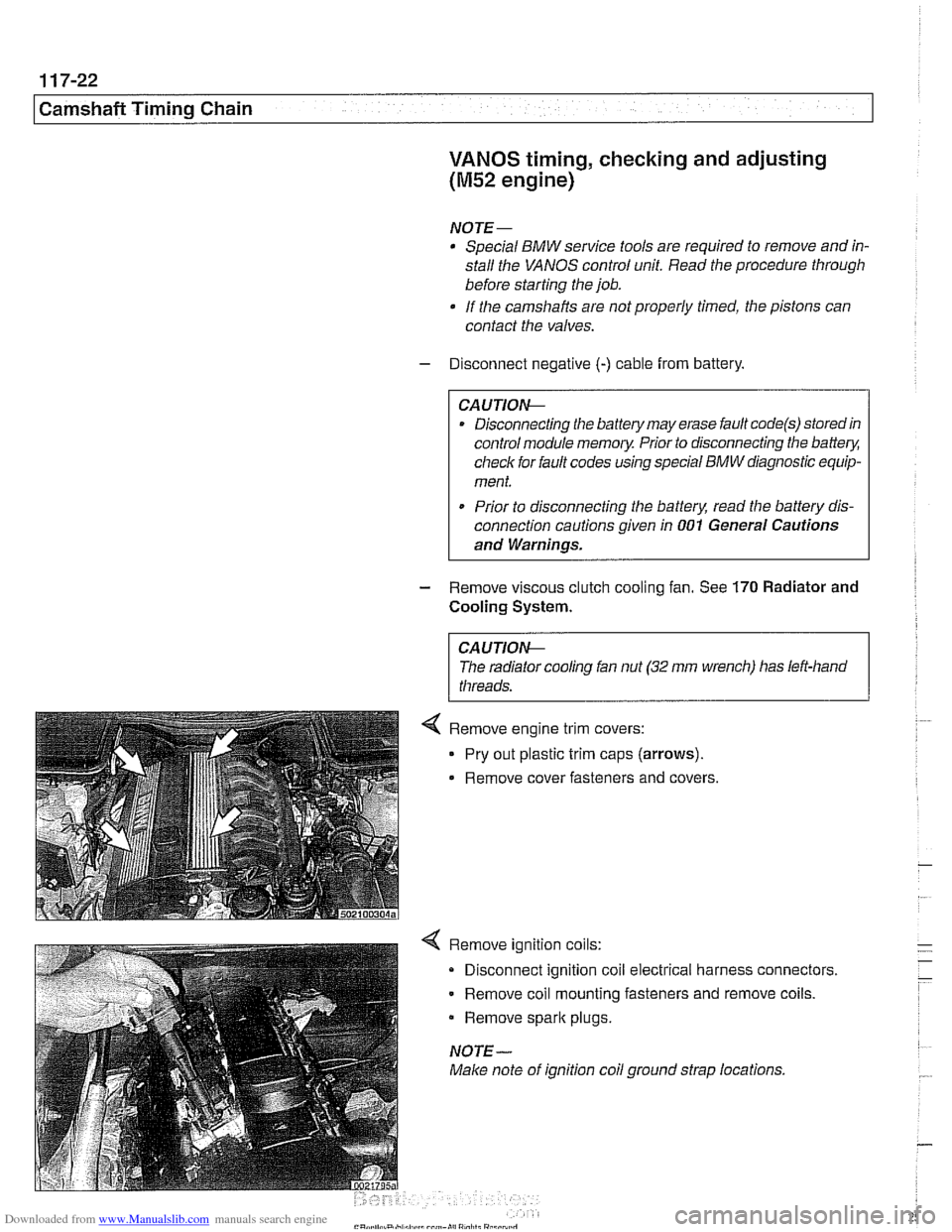
4 Remove ignition coils:
Disconnect ignition coil electrical harness connectors.
Remove coil mounting fasteners and remove coils.
Remove
spark plugs.
NOTE-
Make note of ignition coil ground strap locations.
Page 303 of 1002

Downloaded from www.Manualslib.com manuals search engine
Camshaft Timing chain1
- Disconnect negative cable (-) from battery.
CAUTION-
Prior to disconnecting the battery, read the battery discon-
nection cautions given
in 001 General Cautions and
Warnings.
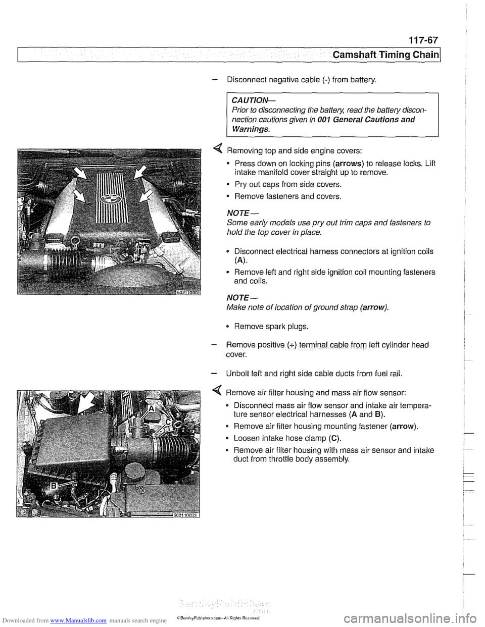
4 Removing top and side engine covers:
Press down on locking pins (arrows) to release locks. Lifl
intake manifold cover straight up to remove.
Pry out caps from side covers.
Remove fasteners
and covers.
NOTE-
Some early models use
pry out trim caps and fasteners to
hold the top cover in place.
Disconnect electrical harness connectors at ignition coils
(A).
Remove left and right side ignition coil mounting fasteners
and coils.
NOTE-
Make note of location of ground strap (arrow).
Remove spark plugs.
- Remove posltlve (+) terminal cable from left cylrnder head
cover.
- Unbolt left and right side cable ducts from fuel rail
Remove air filter housing and mass air flow sensor:
Disconnect mass air flow sensor and intake air tempera-
ture sensor electrical harnesses
(A and B).
Remove air filter housing mounting fastener (arrow)
Loosen intake hose clamp
(C).
Remove air filter housing with mass air sensor and intake
duct from throttle body assembly.
Page 315 of 1002

Downloaded from www.Manualslib.com manuals search engine
Camshaft Timing chain/
Camshaft timing, checking and adjusting
(M62 engine)
WARNING -
Allow engine to cool before beginning this procedure. 1
- Working inside luggage compartment, disconnect negative
battery cable.
CAUTIOI\C
Prior to disconnecting battery cable, read the battery discon-
nection cautions given
in 001 General Cautions and
Warninss.
4 Removing plastic top covers:
Press down on locking pins (arrows) to release locks. Lift
intake manifold cover straight up to remove.
Pry out caps from side covers.
Remove fasteners from beneath
caDs. Lift off covers.
4 Remove air filter housing and ducts:
Disconnect mass air flow sensor and intake air tempera-
ture sensor electrical harnesses
(A and B).
Remove air filter housing mounting fastener (arrow).
Release hose clamp at intake air duct on base of air filter
housing.
Loosen intake hose clamp
(C) and release hose from
mass air flow sensor.
Remove hose at idle air stabilizer.
Release hose clamp at throttle body and remove hose.
Remove upper air filter housing with mass air flow sensor.
- Unbolt left and right side cable ducts from fuel rail.
Page 321 of 1002

Downloaded from www.Manualslib.com manuals search engine
11 9 Lubrication System
General ............................ 11 9-2
Special tools
......................... 11 9-2
..................... Engine lubrication 11 9-3
Troubleshooting .................... 11 9-3
................. Oil pressure. checking 11 9-4
...... Oil pressure warning system. testing 11 9-5
Crankshaft Rear Main Seal ......... .I1 9-6
Crankshaft rear main seal.
replacing (6-cylinder)
.................. 11 9-6
Crankshaft rear main seal. replacing (V-8)
. . 11 9-8
Engine Oil Pan .................... .I1 9-10
Oil pan. removing and
................. installing (6-cylinder) .I1 9-10
Lower oil pan. removing and
installing (V-8)
....................... 1 19-1 3
Upper oil pan. removing and
installing (V-8)
....................... 11 9-1 5
.......... Component Replacement 11 9-20
Oil pressure warning switch. replacing
.................. (6-cylinder and V-8) 11 9-20
Oil level warning switch. replacing
.................. (6-cylinder and V-8) 11 9-21
Oil pump. removing and
................. installing (6-cylinder) 11 9-22
Oil pump. removing and installing (V-8)
. . 11 9-24
..... Oil pressure relief valve (6-cylinder) 119-26
.......... Oil pressure
relief valve (V-8) 11 9-27
Page 323 of 1002

Downloaded from www.Manualslib.com manuals search engine
1 19-3
Lubrication System
V-8 crankshaft rear main seal tool
(Tool No. BMW
11 1 230)
I i 4 V-8 crankshaft rear main seal ouide
4 Adapter for BMW oil pressure gauge
(Tool No. BMW
11 4 050)
Engine lubrication
Oil pressure is generated by a gear-type pump bolted to the
bottom oi the engine block. The oil pump is chain driven off
the front of the crankshaft.
Table a. Engine oil capacity (includes oil filter replacement)
6-cylinder 6.5
liters (6.9
US qt)
V-8 7.5 liters (7.9 US qt)
The oil pressure warning system consists of an oil pressure
switch mounted in the oil circuit and an instrument
panel
warning light. Other saiety features include:
Q A filter bypass to provide lubrication should the oil filter be-
come clogged.
An oil pump pressure relief valve to prevent excessive sys-
tem pressure.
CAUTIOI\C
If the red oil pressure warning light comes on or flashes on
while driving, always assume that the oilpressure is low. Stop
the engine immediately and make arrangements to test oil
pressure.
Page 324 of 1002

Downloaded from www.Manualslib.com manuals search engine
-
I Lubrication System - I
Oil pressure, checking
The oil pressure warning switch is located at the base of the
oil filter housing.
In 6-cylinder engines access to oil pressure warning switch
connector (arrow) is extremely restricted (intake manifold re.
moved for the purpose of illustration).
V-8 engine oil pressure warning switch (arrow) is at base of
oil filter housing on left engine compartment inner fender.
Oil pressure is tested by removing oil pressure switch and in-
stalling oil pressure gauge in its place.
Unscrew oil filter cap in order to allow engine oil to drain back
down into oil pan.
Disconnect harness connector from oil pressure switch and
remove switch.
NOJE-
Thoroughly clean around the oil pressure switch before
removing it.
Be prepared to catch leaking oil with a shop towel.
- Install pressure gauge in place of oil pressure switch,
- With gauge installed, start engine and allow to reach operat-
ing temperature. Check oil pressure. See Table b.
NOJE-
For the most accurate test results, the engine oil and filter
should be new. The oil should be the correct grade.
Table b. Engine oil pressure
At idle 0.5 bar (7 psi)
At elevated speed
6-cylinder engine 4.0 bar
(59 psi)
V-8 engine 4.5 bar (66 psi)