Page 695 of 1002

Downloaded from www.Manualslib.com manuals search engine
Steering and Wheel Alignment
V-8 Sedan (540i)
I Front axle I
Parameter Standard
suspension
Total toe
.
Track (differential angle with 20" ioclc on inside wheel)
Caster (difference between
leftiright maximum 30')
With i 10° wheel loclc
With i 20" wheel lock
Front
wheel displacement
Inside
wheel (approx. ")
Outside wheel (approx. ")
M Sport suspension
Camber (difference between
leitiright maximum 40') 1- 13'i30' 1- 30' i 30' 1- 37' i 30'
0" 10'i 10' 0" 14'ilO'
Sport suspension
0" 14'i 10'
Rear axie
-1°35'i30'
N/A
6" 18'+30'
6' 36' i 30'
0"
i 15'
42
32.6
Total toe
Camber (difference between
IeWright maximum 15')
Geometrical axis deviation ~~
V-8 Sport Wagon (540i)
O"10'iW
-lo 49' i 5'
O"i12'
0" 22' i 4'
-2' 04' i 5'
0"
i 12'
Parameter
-1 " 43 'i 30'
NIA
6" 27'
i 30'
6"49'i30'
Pilo'
41.5
32
0°22'i4'
-2" 04' i 5'
O"i 12'
-ID 44' i 30'
N/A
6" 34' i 30'
6' 50' 130'
0" i 15'
42
31.8
Standard suspension Sport suspension
Front axie
0" 14'210'
-37i30'
-la44'+30'
N/A
6" 34' i 30'
6' 50' i 30'
O0i15'
42
31.8
0"
16'2 10'
-I050'i20'
0" i 12'
Total toe
Camber (difference between
ieftiright maximum 40')
Track (differential angle
with 20" loclc on inside wheel)
Caster (difference between
leftiright maximum 30')
With i 10" wheel lock
With i 20° wheel lock
Front wheel displacement
Inside wheel (approx.
")
Outside wheel (approx. ")
0" 14'i 10'
-13'i30'
-1" 35' i 30'
N/A
6' lS'i30'
6' 36' i 30'
On+ 15'
42 32.65
Rear axle
Total toe
Camber (difference between
lettiright maximum 15')
Geometrical axis deviation
0" 16'i 10'
-I050'i20'
0" i 12'
Page 709 of 1002

Downloaded from www.Manualslib.com manuals search engine
330-1 3
Rear Suspension
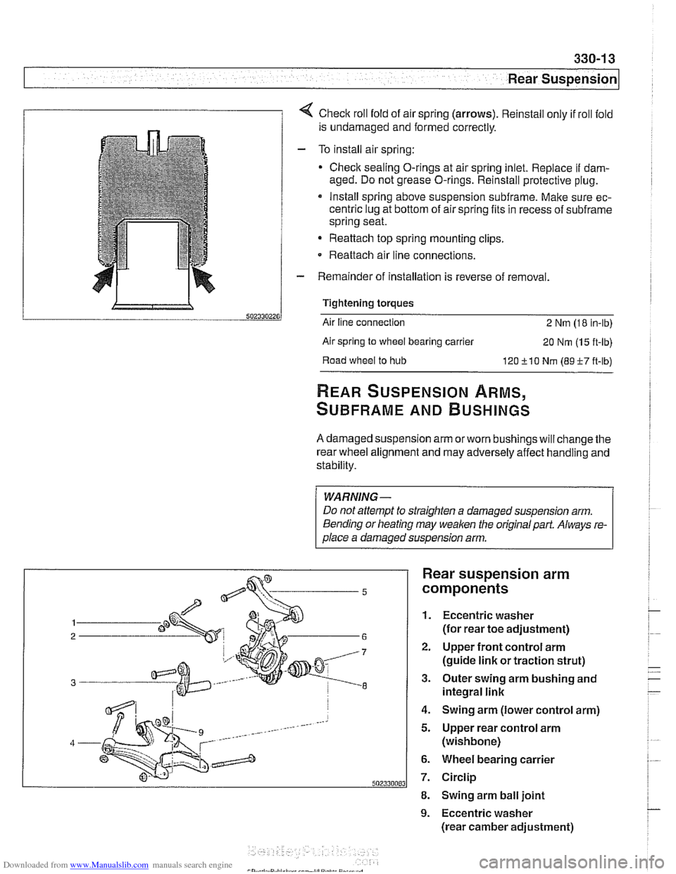
1 1 4 Check roll fold of air spring (arrows). Reinstall only if roll fold
is undamaged and formed correctly.
- To install air spring:
Check sealing O-rings at air spring inlet. Replace
if dam-
aged. Do not grease O-rings. Reinstall protective plug.
* Install spring above suspension subframe. Make sure ec-
centric lug at bottom of air spring fits in recess of
subframe
spring seat.
Reattach top spring mounting clips.
- Reattach air line connections.
- Remainder of installation is reverse of removal.
Tightening torques
Air line connection
2 Nm (1 8 in-lb)
Air spring
to wheel bearing carrier 20 Nm (1 5 ft-lb)
Road
wheel to hub 120 510 Nm (89-F-7 ft-lb)
REAR SUSPENSION ARMS,
SUBFRAME AND BUSHINGS
A damaged suspension arm orworn bushings will change the
rear wheel alignment and may adversely affect handling and
stability.
WARNING-
Do not attempt to straighten a damaged suspension arm.
Bending or heating may
weaken the original part. Always re-
olace a damaoed susoension arm.
Rear suspension arm
components
1. Eccentric washer
(for rear toe adjustment)
2. Upper front control arm
(guide link or traction strut)
3. Outer swing arm bushing and
integral link
4. Swing arm (lower control arm)
5. Upper rear control arm
(wishbone)
6. Wheel bearing carrier
7. Circlip
8. Swing arm ball joint
9. Eccentric washer
(rear camber adjustment)
Page 728 of 1002

Downloaded from www.Manualslib.com manuals search engine
I Rear Suspension
4 When installing subframe bushing, be sure alignment arrows
point front and rear.
Coat new mount with
CircolightB anti-friction agent.
< Draw new bushing into subframe using BMW special tools 33
4152,334153,334154,334155,334157.
- Remainder of installation is reverse of removal, noting the fol-
lowing.
* Tighten suspension arm and shock absorber fasteners to
final torque only after vehicle has been lowered and
sus-
oension has settled.
Rear wheel bearing carrier, removing and
installing (sedan models)
- Raise rear end of car and remove wheel
WARNING-
Make sure the car is firmly supported on jaclc stands de-
signed for the purpose. Place
jaclc stands underneath struc-
tural chassis points. Do not place jaclc stands under
suspension parts.
4 With an assistant applying brakes, break free and remove
staked collar nut (arrow).
- Remove brake caliper and brake disc. Hang brake caliper
aside with stiff wire. Do not disconnect brake fluid hose. See
340 Brakes.
- Disconnect parking brake cable from brake shoe expander.
See 340 Brakes.
Page 790 of 1002
Downloaded from www.Manualslib.com manuals search engine
340-28
Brakes
- Remove sensor mounting screws. Lift sensor away from
bracket.
- Installation is reverse of removal.
CAUTION-
Be sure to tighten the DSC acceleration sensor(s) and
mounting bracket, if applicable, to specified torques. The
sensor
is vibration sensitive and subject to cause DSC
malfunctions if installed improperly.
a After replacing the sensor, perform sensor adjustment
using either DIS or
MoDiC under Service Functions
menu.
Tightening
torques
Lateral acceleration I rotational rate sensor 8 Nm (6 R-ib)
to bracket
Sensor bracket to body
8 Nm (6 ft-lb)
DSC steering angle sensor, removing and
installing
4 Remove lower dash panel mounting fasteners (A) and (5).
- Remove steering column lower trim panel. See 320 Steering
and Wheel Alignment.
Remove steering shaft clamping bolt (arrow).
Disconnect sensor wiring harness connector.
Page 813 of 1002
Downloaded from www.Manualslib.com manuals search engine
Fenders, Engine ~ood/
Hood, removing and installing
With hood open:
Remove hood wiring harness mounting clip
(A)
Disconnect electrical harness connector (B).
Unplug windshield washer hose (C).
WARNING-
The hood is heavy Before removing the hoodsupports, be
sure to have an assistant help
support the hood.
Mark position of hinge plates.
With the help of a assistant, support hood and remove retain-
ing clips
(A) on upper end of pressurized lifting struts. Pull
struts off hood.
Loosen upper hinge bolts
(B)
Remove lower hinge bolts (C). Lift hood off carefully.
Installation is reverse of removal.
* Repair any paint damage and paint any exposed metal
Check hood alignment. See
Hood, aligning.
NOTE-
The hood was fitted and attached to an unfinished body at
the factory Unfinished
sun'aces exposed by this procedure
must be touched up with paint,
Page 817 of 1002

Downloaded from www.Manualslib.com manuals search engine
Fenders, Ensine HOO~I
Hood release cable and spring pins,
adjusting
Before adjusting hood pins, be sure the hood is aligned even-
ly to fenders and front panel.
- Malte sure bowden cable, which connects both hood loclts
together, is seated in lock guide on both left and right loclts.
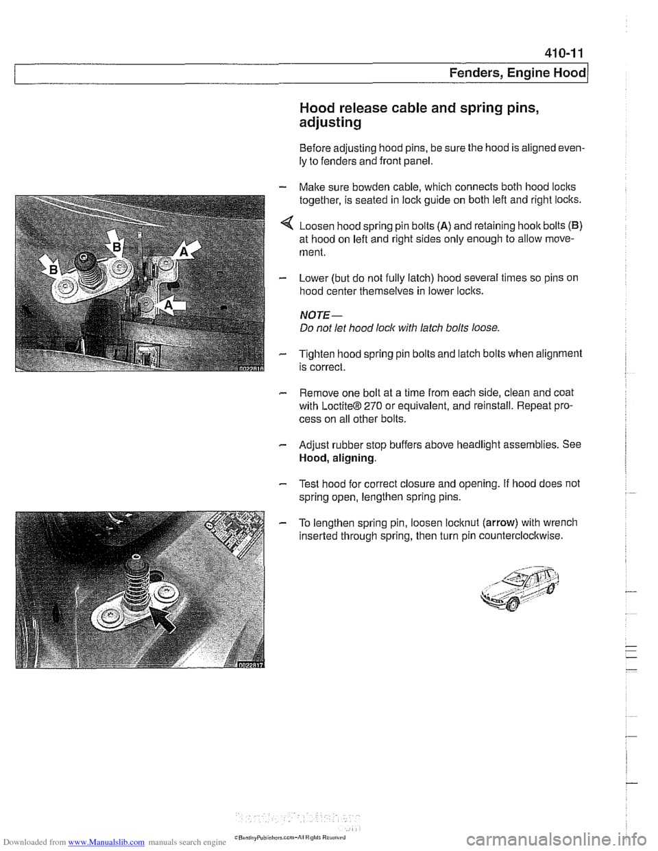
4 Loosen hood spring pin bolts (A) and retaining hoolt bolts (B)
at hood on left and right sides only enough to allow move-
ment.
- Lower (but do not fully latch) hood several times so pins on
hood center themselves in lower loclts.
NOTE-
Do not let hood lock with latch bolts loose
- Tighten hood spring pin bolts and latch bolts when alignment
is correct.
- Remove one bolt at a time from each side, clean and coat
with
LoctiteB 270 or equivalent, and reinstall. Repeat pro-
cess on all other bolts.
- Adjust rubber stop buffers above headlight assemblies. See
Hood, aligning.
- Test hood for correct closure and opening. If hood does not
spring open, lengthen spring pins.
- To lengthen spring pin, loosen locltnut (arrow) with wrench
inserted through spring, then turn pin counterclocltwise.
Page 829 of 1002
Downloaded from www.Manualslib.com manuals search engine
41 2 Trunk Lid. Tailgate
........................... General
......................... Trunk Lid
Trunlc lid. removing and installing ........
Trunk lid. adjusting ...................
Trunk lid support strut.
removing and installing
................
Tailgate (Sport Wagon Models) .....
Tailgate. emergency release ...........
Tailgate and window strut diagram .......
Window strut removal diagram .......... 412-8
Rear window gas strut.
removing and installing
................ 412-9
Tailgate gas strut. removing and installing
............... 412-10
Tailgate. removing and installing
........ 412-1 1
Rear window. removing and installing
.... 412-12
Rear window and tailgate. alignment
..... 412-13
Page 840 of 1002

Downloaded from www.Manualslib.com manuals search engine
Trunk Lid, Tailgate I
4 Remove rubber grommet and applicable connectors. Discon-
nect rear window washer hose.
NOTE-
To facilitate installation, mark position of hinges for tailgate
and rear window frame on body
WARNING-
The tailgate is very heavy and will close without both pres-
surized lifting struts installed. Properly support tailgate pri-
or to removal of the lifting struts.
There is risk of fingers being trapped once tailgate fas-
teners are removed.
CAUTION-
Protect body opening for tailgate with fabric tape.
4 Remove hinge fasteners for tailgate and rear window frame.
Lower tailgate so that hinge for tailgate and rear window
can be tilted.
- Tilt hinge for tailgate and rear window frame so that tailgate
can be moved towards the rear with rear window frame.
- Remove tailgate with rear window frame towards rear.
- Installation is the reverse of removal
Rear window, removing and installing
- Disconnect electrical harnesses.
- Support window in open position.
Loosen fasteners on each window hinge.
NOTE-
Note positions of any spacers for reinstallation
CAUTION-
Rear window is heavy Use a second person to support win-
dow prior to releasing from hinges.
- Remove window hinge fasteners and lift off window.
- Installation is reverse of removal. Replace waterprooiing
sheeting where disturbed.
See Rear window and tailgate, alignment.