Page 662 of 1002

Downloaded from www.Manualslib.com manuals search engine
I Steerina and Wheel Alianment
Steering
system
Two types of steering gear are used in the E39 series models.
6-cylinder
(5251, 528i and 530i) models are equipped with
rack and pinion steering. The steering rack is mounted to
an aluminum subframe.
V-8
(540i) models are equipped with a recirculating ball
and nut steering gearbox mounted to a steel subframe.
At low speeds, maximum power assist is provided to ease
parking and city driving. At high speeds, assist is reduced to
ensure stability. The power steering system varies assist
based on engine speed.
Power boost for the steering is provided by an engine-driven
hydraulic pump. A hydraulic control valve is used to control
boost pressure.
The steering wheel connects to the steering gear via an ad-
justable steering column which incorporates a rubber cou-
pling ("guibo") to dampen vibration and noise.
Power steering fluid is supplied from the fluid
reservoir to the
pump and to the steering gear via rubberlmetal hoses.
The return line from the steering gear to the
reservoir loops
into the airstream in front of the radiator and connects to the
steering fluid cooler. The fluid cooler is attached to a cassette
which also includes cooling coils for engine oil, transmission
fluid and AIC condenser.
The steering gear requires no maintenance other than align-
ment and periodic inspection for worn components. Inspect
rubber rack boots
(rack and pinion system) and tie-rod end
boots periodically for tears or damage. Replace
if necessary.
-
NOTE-
The airbag system is traditionally referred to as Supplemen-
tal Restraint System (SRS). The
BMW versfon of SRS used
m the E39 models is known as the Multiple Restraint System - (MRS). - -
Page 663 of 1002
Downloaded from www.Manualslib.com manuals search engine
Steering and Wheel Alignment
I Rack and r in ion steering 1 Steering system variations
I 6-~~linder'rnodels (525i,>28i, 530i) / 1. Left tie rod
2. Right tie rod
3. Steering rack
4. Steering gearbox
5. idler arm
6. Center tie rod
7. Steering knuckle
Recirculating ball and nut steering
r V-8 models 154Oib
Page 672 of 1002

Downloaded from www.Manualslib.com manuals search engine
320-1 4
Steering and Wheel Alignment
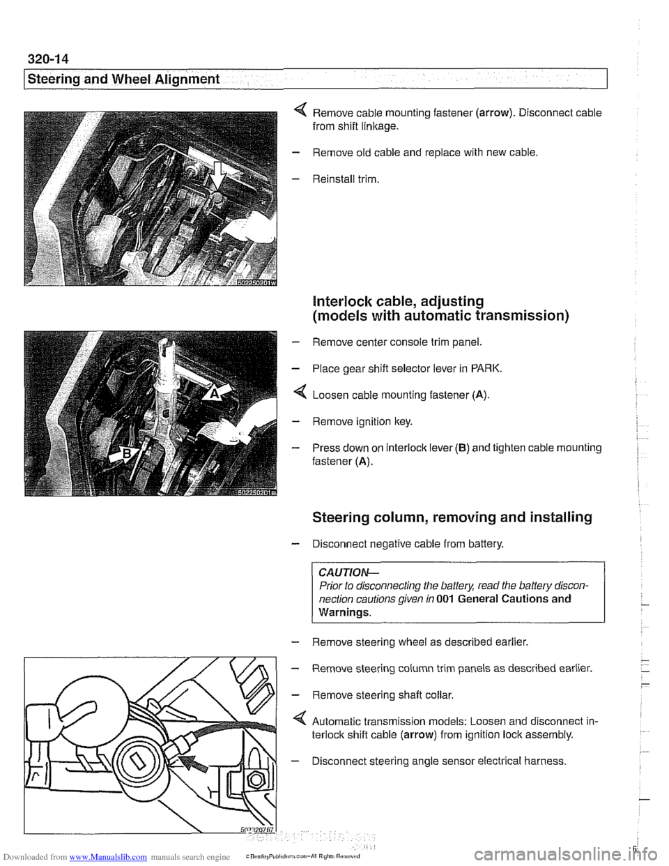
Remove cable mounting fastener (arrow). Disconnect cable
from shift
linkage.
Remove old cable and replace with new cable.
Reinstall trim.
Interlock cable, adjusting
(models with automatic transmission)
- Remove center console trim panel.
- Place gear shift selector lever in PARK.
4 Loosen cable mounting fastener (A).
- Remove ignition key.
- Press down on interlock lever (B) and tighten cable mounting
fastener (A).
Steering column, removing and installing
- Disconnect negative cable from battery.
CAUTIOI\C
Prior to disconnecting the battea read the battery discon-
nection cautions given
in 001 General Cautions and
Warninqs.
- Remove steering wheel as described earlier.
m
- Remove steering column trim panels as described earlier.
' \L/>I - Remove steerinq shaft collar
Automatic transmission models: Loosen and disconnect in-
terlock shift cable (arrow) from ignition lock assembly.
4 - Disconnect steering angle sensor electrical harness.
Page 682 of 1002
Downloaded from www.Manualslib.com manuals search engine
Steering and Wheel Alignment
Tightening torques
Tie rod
to Steering knuckle (replace self-locking nut) 65 Nm (48 it-lb)
to Steering rack 71 Nrn (52 ft-lb)
Outer tie rod end lock nut 51 Nrn (38 ft-lb)
Refer to the steering components illustration when perform-
ing the procedures below.
Steering gearbox system
components
(V-8 models
up to
911 999)
1. Tie rod end nut
2. Washer
3. Tie rod end
4. Steering fluid cooler
5. Tie rod end clamp bolt
6. Nut
7. ldler arm
8. ldler arm bushing
9. ldler arm bolt
10. Steering fluid reservoir
11. Hose clamp
12. Fluid supply line
13. Power steering pump
14. Fluid return line
15. O-ring seal
16. Banjo bolt
17. High pressure line
18. Center tie rod
19. Nut
20. Pitman arm
21.
Pitman arm pinch bolt
22. Nut
23. Fluid cooler supply line
24. Steering gearbox
Page 683 of 1002

Downloaded from www.Manualslib.com manuals search engine
Steering and Wheel ~li~nrnentl
Steering gearbox, removing and installing
- Disconnect negative (-) battery cable. See 020 Mainte-
nance.
CAUTION-
Prior to disconnecting the battew read the battery discon-
nection cautions given in
001 General Cautions and
Warnings.
- Remove airbag unit from steering wheel. See 721 Airbag
System (SRS).
WARNING -
Improper handling of the airbag could cause serious injury
Store the
airbag with the horn pad facing up. If stored lacing
down, accidental deployment couldpropel it violently info the
air, causing
injuv
- Remove steering wheel as described earlier.
- Drain power steering system reservoir.
- Raise front of car.
WARNING -
Make sure the car is firmly supported on jack stands de-
signed for the purpose. Place jack stands beneath structural
chassis points. Do not place jack stands under suspension
Darts.
- Remove heat shield from left side of subframe.
- Remove fluid hoses from top of steering gearbox. Immedi-
ately plug all fluid openings.
Remove and discard
pitman arm self-loclting nut (arrow).
Page 684 of 1002

Downloaded from www.Manualslib.com manuals search engine
Steering and Wheel Alignment
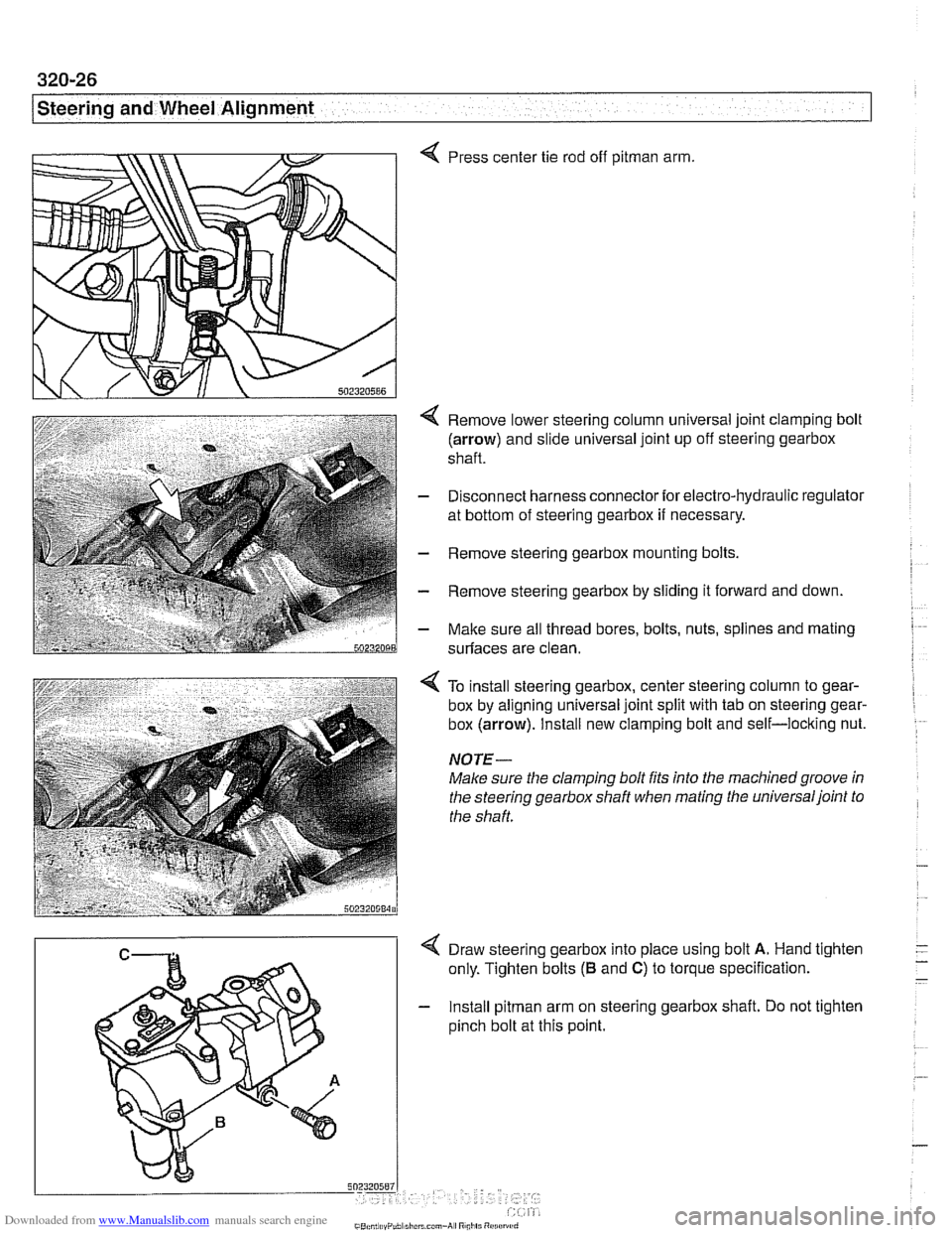
Press center tie rod off pitman arm.
Remove lower steering column universal joint clamping bolt
(arrow) and slide universal joint up off steering gearbox
shaft.
Disconnect harness connector for electro-hydraulic regulator
at bottom of steering gearbox
if necessary.
Remove steering gearbox mounting bolts
Remove steering gearbox by sliding it forward and down.
Malte sure all thread bores, bolts, nuts, splines and mating
surfaces are clean.
4 To install steering gearbox, center steering column to gear-
box by aligning universal joint split with tab on steering gear-
box
(arrow). Install new clamping bolt and self-locking nut.
NOTE-
Make sure the clamping bolt fits into the machinedgroove in
the steering gearbox shaft when mating the universaljoint to
the shaft.
4 Draw steering gearbox into place using bolt A. Hand tighten
only. Tighten bolts
(B and C) to torque specification.
- Install pitman arm on steering gearbox shaft. Do not tighten
pinch bolt at this point.
Page 685 of 1002

Downloaded from www.Manualslib.com manuals search engine
L.. Steering and Wheel ~li~nrnentl ~
4 Mark A on steering gearbox shaft must be located in center
of
pitman arm slot.
- Adjust pitman arm as described later.
I 5"?~~5~"
I / < Gap A = 0.5 - 8.5 mm (0.02 - 0.33 in)
- Tighten pitman arm pinch bolt to specification.
' 1 Tightening torques
I u "steering Steering gearbox to subframe 62 Nm (46 ft-lb)
box Steering shaft universal joint to steering 19 Nm (14 It-lb)
gearbox (replace bolt)
- Install center tie rod to pitman arm using a new self locking
Pilrnan nut. arm
5nz3zn588 - Connect harness connector for Servotronic electro-hydraulic
regulator
if necessary.
- Connect fluid hoses to steering gearbox. Use new sealing
washers at couplings and make sure not to overtorque banjo
bolts.
Tightening torques Hydraulic lines to steering gearbox (banjo bolts)
MI0 12 Nm (9 ft-lb)
- M14 35 Nm (26 ft-lb)
. M16 40 Nm (30 ft-lb)
MI8 45 Nm (33 it-lb)
Center tie rod to pitrnan arm 65 Nm (48 it-lb)
(use new self-loclting nut)
- Reconnect negative (-) battery cable.
- lnstall airbag unit. See 721 Airbag System (SRS).
- Fill and bleed power steering system as described earlier.
Page 686 of 1002

Downloaded from www.Manualslib.com manuals search engine
320-28
[steering and Wheel Alignment
Pitman arm, removing and installing
- Raise front of car. Remove splash shield from under engine.
Male sure the car is
firmly supported on jack stands de-
signed for the purpose. Place jack stands beneath structural
chassis points. Do not place
jaclc stands under suspension
parts.
4 Set steering wheel in straight ahead position with tab (arrow)
aligned with mark on steering gearbox.
Remove center tie rod fastener and press tie rod out of pit.
man arm with BMW special
too1 32 1 190.
- Loosen and remove pitman arm pinch bolt
4 Mark A on steering gearbox shalt must be located in center
of
pitman arm slot.
- Reinstall center tie rod and tighten nut.
- Adjust pitman arm height as described later.
- Have vehicle professionally aligned.
Tightening torques
50:s,n5m Center tie rod to pitman arm 65
Nm (48 ft-lb)
(use new self-locking nut)
Pitman arm pinch bolt (note direction of threads) 61 Nrn (45 ft-lb)