Page 365 of 1002
Downloaded from www.Manualslib.com manuals search engine
Ignition System
Remove intake manifold as described in 113 Cylinder Head
Remaval and Installation.
Remove knock sensor mounting bolts (arrows) on side of
cylinder block. Remove sensors.
I CAUTION- I
Note the installedangle of the knock sensors on the bloclt be-
fore removalit. Reinstall the sensors in the same position. Be
sure to use
a torque wrench when tightening the sensor
mounting bolts.
Clean
lknoclc sensor contact surfaces on engine bloclc and
sensors before installing.
Tightening torque
Knock sensor to engine
bloclc 20 Nm (15 ft-lb)
- Use scan tool to read out and clear ECM fault memory.
- Installation is reverse of removal.
Page 367 of 1002

Downloaded from www.Manualslib.com manuals search engine
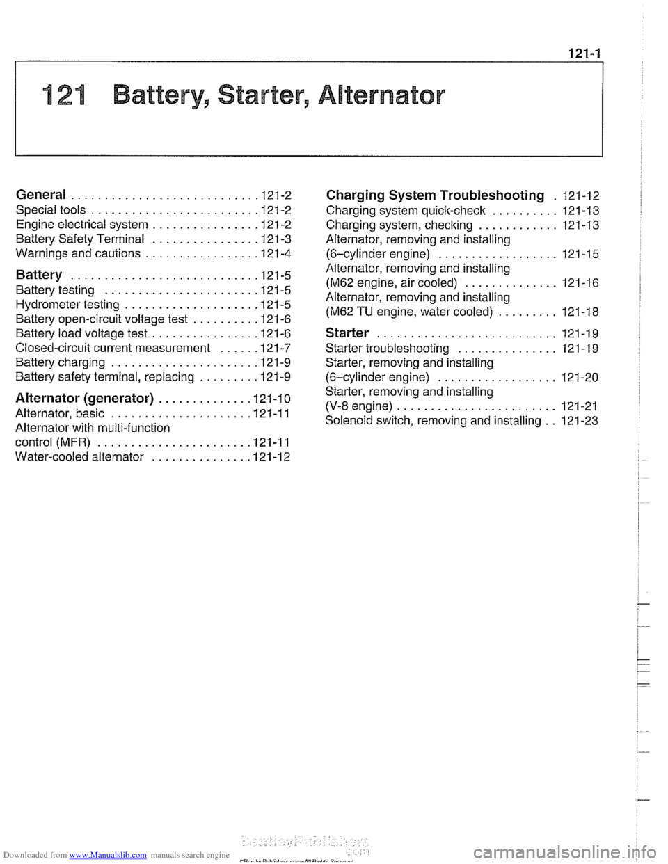
121-1
121 Battery. Starter. Alternator
General ........................... .I2 1.2
Special tools ........................ .I2 1.2
Engine electrical system ............... .I2 1.2
Battery Safety Terminal ............... .I2 1.3
Warnings and cautions ................. 121 -4
Battery ............................ 121-5
Battery testing ...................... .I2 1.5
Hydrometer testing ................... .I2 1.5
Battery open-circuit voltage test ......... .I2 1.6
Battery load voltage test ................ 121 -6
Closed-circuit current measurement ..... .I2 1.7
Battery charging ...................... 121 -9
Battery safety terminal, replacing ......... 121-9
Alternator (generator) ............. .I2 1.10
Alternator. basic .................... .I2 1.11
Alternator with multi-function
control (MFR)
...................... .I2 1.11
Water-cooled alternator ............... 121 -12
Charging System Troubleshooting . 121-12
Charging system quick-check .......... 121-13
Charging system. checking ............ 121-13
Alternator. removing and installing
(6-cylinder engine)
.................. 121 -1 5
Alternator. removing and installing
(M62 engine. air cooled)
.............. 121-16
Alternator. removing and installing
(M62 TU engine. water cooled) ......... 121-1 8
Starter ........................... 121 -1 9
Starter troubleshooting ............... 121 -1 9
Starter. removing and installing
(6-cylinder engine)
.................. 121-20
Starter. removing and installing
(V-8 engine)
........................ 121 -21
Solenoid switch. removing and installing . . 121-23
Page 381 of 1002

Downloaded from www.Manualslib.com manuals search engine
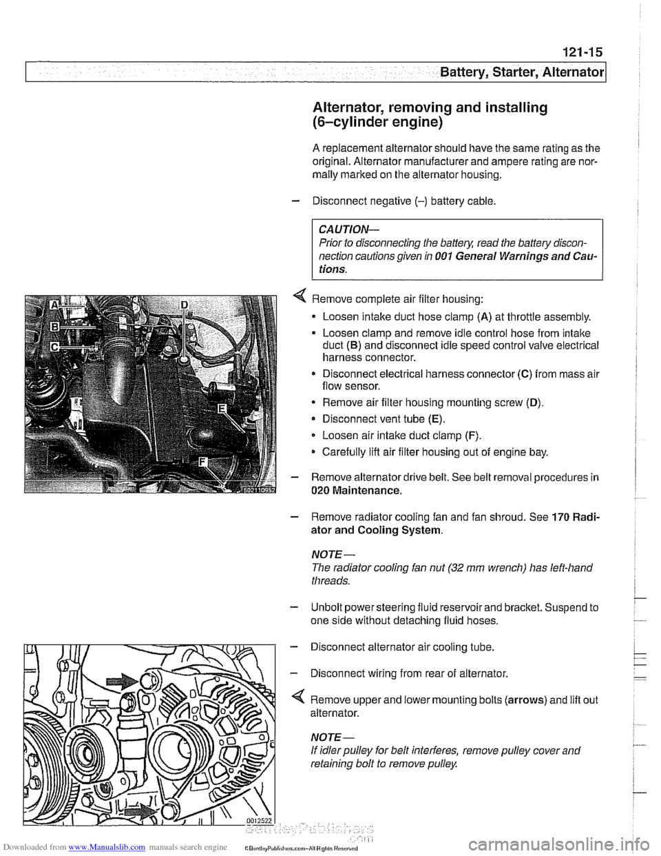
Battery, Starter, ~lternatorl
Alternator, removing and installing
(6-cylinder engine)
A replacement alternator should have the same rating as the
original. Alternator manufacturer and ampere rating are nor-
mally marked on the alternator housing.
- Disconnect negative (-) battery cable.
CAUTION-
Prior to disconnecting the batteg read the battery discon-
nection cautions given
in 001 General Warnings and Cau-
I tions.
Remove complete air filter housing:
Loosen intake duct hose clamp
(A) at throttle assembly.
Loosen clamp and remove idle control hose from intake
duct
(B) and disconnect idle speed control valve electrical
harness connector.
Disconnect electrical harness connector
(C) from mass air
flow sensor.
* Remove air filter housing mounting screw (D),
Disconnect vent tube (E).
Loosen air intake duct clamp (F).
Carefully lifl air filter housing out of engine bay.
Remove alternator drive belt. See belt removal procedures in
020 Maintenance.
- Remove radiator cooling fan and fan shroud. See 170 Radi-
ator and Cooling System.
NOTE-
The radiator cooling fan nut (32 mm wrench) has left-hand
threads.
- Unbolt power steering fluid reservoir and bracket. Suspend to
one side without detaching fluid hoses.
- Disconnect alternator air cooling tube.
- Disconnect wiring from rear of alternator.
'4 Remove upper and lower mounting bolts (arrows) and lift
alternator.
If idler pulley for belt interferes, remove pulley cover and
retaining bolt to remove pulley. out
Page 382 of 1002

Downloaded from www.Manualslib.com manuals search engine
121-16
Battery, Starter, Alternator
- installation is reverse of removal.
Tightening torques Belt tensloner to engine block
M8 (8.8 grade) 22
Nm (16 ft-ib)
Fan clutch to coolant pump
with BMW special tool 11
5 040 30 Nm (22
ft-lb)
without BMW special tool
11 5 040 40 Nm
(29 ft-ib)
Pulley to alternator 70
Nm (44 ft-lb)
Terminal 30
(B+) wire to alternator (M8) 13 Nm (10 ft-ib)
Alternator, removing and installing
(M62 engine, air cooled)
A replacement alternator should have the same rating as the
original. Alternator manufacturer and ampere rating are nor-
mally
marked on the alternator housing.
- Disconnect negative (-) battery cable.
CAUTION-
Prior to disconnecting the battery, read the battery discon-
nection cautions
001 General Warnings and Cautions.
- Remove cooling fan and alternator drive belt. See 020 Main-
tenance.
- Pry out trim caps and remove fasteners from plastic cover on
left head. Lift off cover.
Disconnect positive
(+) lead from jump start post (arrow).
Raise car and support in a safe manner.
WARNING-
Make sure the car is stable and well supported at aN times.
Use a professional automotive lift
orjack stands designed for
the purpose.
A floorjack is not adequate support.
Page 384 of 1002

Downloaded from www.Manualslib.com manuals search engine
121-18
I Battery, Starter, Alternator
Alternator, removing and installing
(M62 TU engine, water cooled)
V-8 models produced after 9/98 are equipped with a water
cooled alternator.
CAUTION-
Allow engine to cool before removing alternator as coolant
will
escape from the alternator water jacket.
- Disconnect negative (-) battery cable
CAUTION- Prior to disconnecting the
battew read the battery discon-
nection cautions given in
001 General Warnings and Cau-
tions.
- Remove radiator cooling fan and fan shroud. See 170 Radi-
ator and Cooling System.
- Drain engine cooling system. See 170 Radiator and Cool-
ing System.
- Remove alternator drive belt. See 020 Maintenance.
- Disconnect battery lead (terminal 30 or B+) and two-pin har-
ness connector from front of alternator.
I < Remove bolts securing alternator to water jacket and remove
aling ring
alternator.
NOTE- If necessary, raise car and remove engine compartment
splash shield to access lower alternator mounting bolts.
The upper coolant hose can also
be removed to assist al-
ternator removal.
Page 386 of 1002

Downloaded from www.Manualslib.com manuals search engine
I Battery, Starter, Alternator
- Check for battery voltage at terminal 50 of starter motor with
key in start position. If voltage is not present, check wiring be-
tween ignition switch and starter terminal. Check the EWS
system and other inputs that disrupt terminal
56 to the start-
er. See ELE Electrical
Wiring Diagrams. If voltage is
present and no other visible wiring faults can be found, prob-
lem is most likely in starter motor.
Starter, removing and installing
(6-cylinder engine)
The starter is removed from below. Access to starter bolts is
difficult. Be sure to have the proper tools on hand before pro-
ceeding.
NOTE-
Access to the starter wiring is very limited. Forbetteraccess,
it may be necessary to remove the intake manifold.
- Disconnect negative (-) battery cable.
CAUTIOI\C
Prior to disconnecting the battern read the baltery discon-
nection cautions
in OOlGeneral Cautions and Warnings.
Remove complete air filter hous~ng:
Loosen intake duct hose clamp (A) at throttle assembly.
Loosen clamp and remove idle control hose from intake
duct
(B) and disconnect idle speed control valve electrical
harness connector.
Disconnect electrical harness connector
(C) from mass air
flow sensor.
Remove air filter housing mounting screw (D)
Disconnect vent tube
(E).
Loosen air intake duct clamp (F).
Carefully lift air filter housing out of engine bay.
Disconnect throttle cable.
Raise vehicle and support safely.
WARNING-
Make sure the car is stable and well supported at all times.
Use a professional automotive
lift orjack stands designed for
the purpose. A
floorjaclc is not adequate support
- Working underneath car, remove engine splash shield
- Disconnect fuel lines and harness connectors from retaining
brackets, as necessary.
Page 387 of 1002

Downloaded from www.Manualslib.com manuals search engine
Battery, Starter, ~lternatorl
- Disconnect wiring from starter.
4 Note routing for cables. Routing varies depending on model
and transmission. When reinstalling, make sure cables do
not chafe.
- Using a long extension and universal joint from output end of
transmission, remove bolts fastening starter to transmission
bell housing and engine block.
- Remove starter from below
4 Checlc starter pinion gear and flywheel teeth for damage.
- Installation is reverse of removal.
Tightening torques
Starter to engine 47 Nrn (35 It-lb)
Starter sipport bracket to starter 5 Nrn (44 in-lb)
Starter support
bracket to engine 47 Nrn (35 ft-lb)
Wlre terminals to slarter
M5 5 Nrn (44 in-lb)
M6 7 Nrn (62 in-lb)
M8 13 Nrn (10 ft-lb)
Starter, removing and installing
(V-8 engine)
The starter is on the right (passenger) side of the engine, and
is removed from below. Access to starter bolts is difficult. Be
sure to have the proper tools on hand before proceeding.
- Disconnect negative (-) battery cable
CA UTIOW-
Prior to disconnecting the battery, read the battev discon-
nection cautions in
OOlGeneral Cautions and Warnings. -
- Raise vehicle and support safely.
/ WARNING- 1 ~ ~~ ~~ ~~~ ~
Make sure the car is stable and well supported at all times.
Use a professional automotive lift orjacltstands designed for
I the purpose. A floor jack is not adequate support I
Page 389 of 1002
Downloaded from www.Manualslib.com manuals search engine
121-23
Battery, Starter, ~lternatorl
Solenoid switch, removing and installing
- Remove starter as described previously.
- Disconnect field winding strap between starter motor and
solenoid switch.
NOTE-
If the field winding strap is damaged or burned, a new or
rebuilt starter motor is needed.
< Remove solenoid switch mounting screws (arrows), and
separate solenoid from starter.
Unhoolc solenoid plunger from lever in starter drive
- Installation is reverse of removal. Lubricate solenoid piston
with light grease.
CAUTION- When installing field winding strap to starter, position
itso that
it does not contact the starter body.
Tightening torque
Field strap to starter
13 Nm (10 ff-lb)