2000 BMW 528i idle air control valve
[x] Cancel search: idle air control valvePage 76 of 1002

Downloaded from www.Manualslib.com manuals search engine
11 0-4
/Engine Removal and Installation
- Disconnect negative (-) cable from battery.
CAUTION- Prior to disconnecting the
batteg read the battery discon-
nection cautions
in 001 General Cautions and Warnings.
- Remove engine hood, or place in service position. See 410
Fenders, Engine Hood.
4 Remove left and right interior ventilation ducts (lefl side
shown):
Release ventilation filter cover latch (A) and remove cover.
Release plastic loclting tab
(6) or release locking tabs on
top of duct (later models).
Rotate duct counterclocltwise to
unloclt from bulkhead and
remove (arrow).
Disconnect electrical harness from hood switch (C).
Release spring
loclt (D).
Slide filter housing away from inner fender to remove.
Removal of right side ventilation duct is similar.
Remove rear bulkhead panel:
Remove rubber sealing gasket (arrow).
- Remove 3 mounting clips (A).
Remove
4 retaining screws (6).
Lift off panel.
Remove complete air filter housing:
Loosen
intalte duct hose clamp (A) at throttle assembly.
Loosen clamp and remove idle control line from intalte duct
(6) and (where applicable) disconnect idle speed control
valve electrical harness connector.
Disconnect harness connector (C) from mass air flow sen-
sor.
Remove air filter housing mounting screw (D).
Disconnect vent tube
(E).
Loosen air intake duct clamp (F).
Carefully lift air filter housing out of engine bay.
Page 103 of 1002

Downloaded from www.Manualslib.com manuals search engine
11 3-9
Cylinder Head Removal and Installation
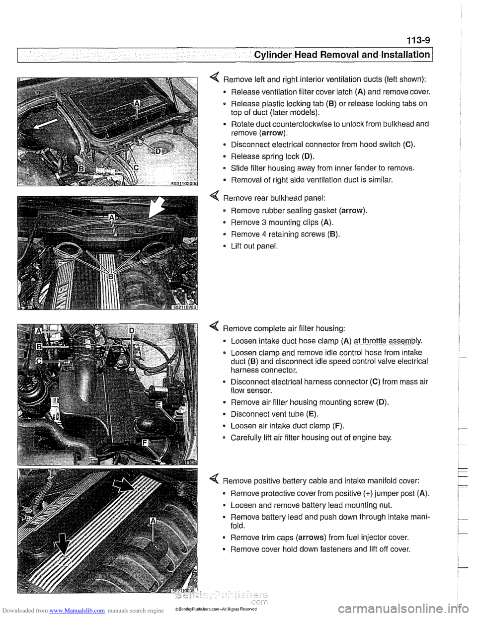
< Remove left and right interior ventilation ducts (left shown):
Release ventilation filter cover latch (A) and remove cover.
Release plastic locking tab
(6) or release locking tabs on
top of duct (later models).
Rotate duct counterclockwise to unlock from bulkhead and
remove (arrow).
Disconnect electrical connector from hood switch
(C).
Release spring lock (D).
Slide filter housing away from inner fender to remove.
Removal of right side ventilation duct is similar.
Remove rear bulkhead panel: Remove rubber sealing
gasket (arrow).
0 Remove 3 mounting clips (A).
Remove
4 retaining screws (6).
Lift out panel.
< Remove complete air filter housing:
Loosen
intake duct hose clamp (A) at throttle assembly.
Loosen clamp and remove idle control hose from
~ntake
duct (6) and disconnect Idle speed control valve electr~cal
harness connector.
Disconnect
electr~cal harness connector (C) from mass alr
flow sensor.
Remove air filter housing mounting screw (D).
Disconnect vent tube
(E).
Loosen air intake duct clamp (F).
Carefully lift air filter housing out of engine bay.
4 Remove positive battery cable and intake manifold cover:
Remove protective cover from positive (+)jumper post (A).
Loosen and remove battery lead mounting nut.
Remove battery lead and push down through intake mani-
fold.
Remove trim caps (arrows) from fuel injector cover.
Remove cover hold down fasteners and lift off cover.
Page 117 of 1002

Downloaded from www.Manualslib.com manuals search engine
- --
Cylinder Head Removal and Installation 1 --
< Remove complete air filter housing assembly with mass air
flow sensor:
Loosen
intalte duct hose clamp (A) at throttle assembly.
Loosen clamp and remove idle control line from intake duct
(B) and disconnect idle speed control valve electrical har-
ness connector.
Disconnect electrical harness connector
(C) from mass air
flow sensor.
Remove air filter housing mounting screw
(D).
Disconnect vent tube (E).
. Loosen air intalte duct clamp (F).
Carefully lifl air filter housing, mass air flow sensor, and in-
take duct hose out of engine bay.
4 Disconnect positive battery cable and remove intake rnani-
fold cover:
Remove protective cover from positive (+)jumper post.
Loosen and remove battery lead mounting nut (A).
Remove lead and push down through intake manifold.
* Remove trim covers (arrows) from fuel injector cover.
Remove cover hold down fasteners and lifl off cover.
4 Worlting above engine, disconnect the following:
Vent line from cylinder head cover. To remove, pinch clips
(arrows).
Electrical harness connector from VANOS solenoid valve
(A).
- Remove oxygen sensors and exhaust manifolds. See 180
Exhaust System.
CAUTION-
Remove oxygen sensors before removing exhaust mani-
fold to prevent damage.
Label oxygen sensor harness connectors so that they
can be reassembled correctly Do not interchange con-
nectors.
NOTE-
Front exhaust manifold must be removed before rear
manifold.
Page 379 of 1002

Downloaded from www.Manualslib.com manuals search engine
Battery, Starter, ~lternatorl
Charging system quick-check
Use a digital multimeter to measure voltage across the bat-
tery terminals with key off and then again with engine running.
Battery voltage should be about 12.6 volts with key off and be-
tween 13.5 and 14.5 volts with engine running.
NOTE-
The regulated voltage (engine running) should be between
13.2 and 14.5, depending on temperature andoperating con-
ditions.
If the voltage is higher than 14.8, the voltage regula-
tor or
mulitfunction controller is most likely faulty
Check for clean and tight battery cables. Check ground cable
running from negative
(-) battery terminal to chassis and
ground cable running from engine to chassis. Check alterna-
tor drive belt condition and tension.
Charging system, checking
CAUTIOI\C
* Do not disconnect the battery while the engine is running.
Damage to the alternator and/or engine electronic systems
may result.
Only use a digital multimeter when testing charging
system components.
--7
4 Turn ignition key on. Check that battery warning light comes
on.
NOTE-
If the warning light does not come on, repair bulb or wiring
faults before continuing to checlc the charging system.
/ Charge indicator
502820805
4 6-cylinder engines only, remove complete air filter housing:
Loosen
intake duct hose clamp (A) at throttle assembly.
Loosen clamp and remove idle control hose from intake
duct
(B) and disconnect idle speed control valve electrical
harness connector.
Disconnect electrical harness connector
(C) from mass air
flow sensor.
Remove air filter housing mounting screw
(D).
Disconnect vent tube (E).
Loosen air intake duct clamp (F).
Carefully lift air filter housing out of engine bay.
Page 381 of 1002

Downloaded from www.Manualslib.com manuals search engine
Battery, Starter, ~lternatorl
Alternator, removing and installing
(6-cylinder engine)
A replacement alternator should have the same rating as the
original. Alternator manufacturer and ampere rating are nor-
mally marked on the alternator housing.
- Disconnect negative (-) battery cable.
CAUTION-
Prior to disconnecting the batteg read the battery discon-
nection cautions given
in 001 General Warnings and Cau-
I tions.
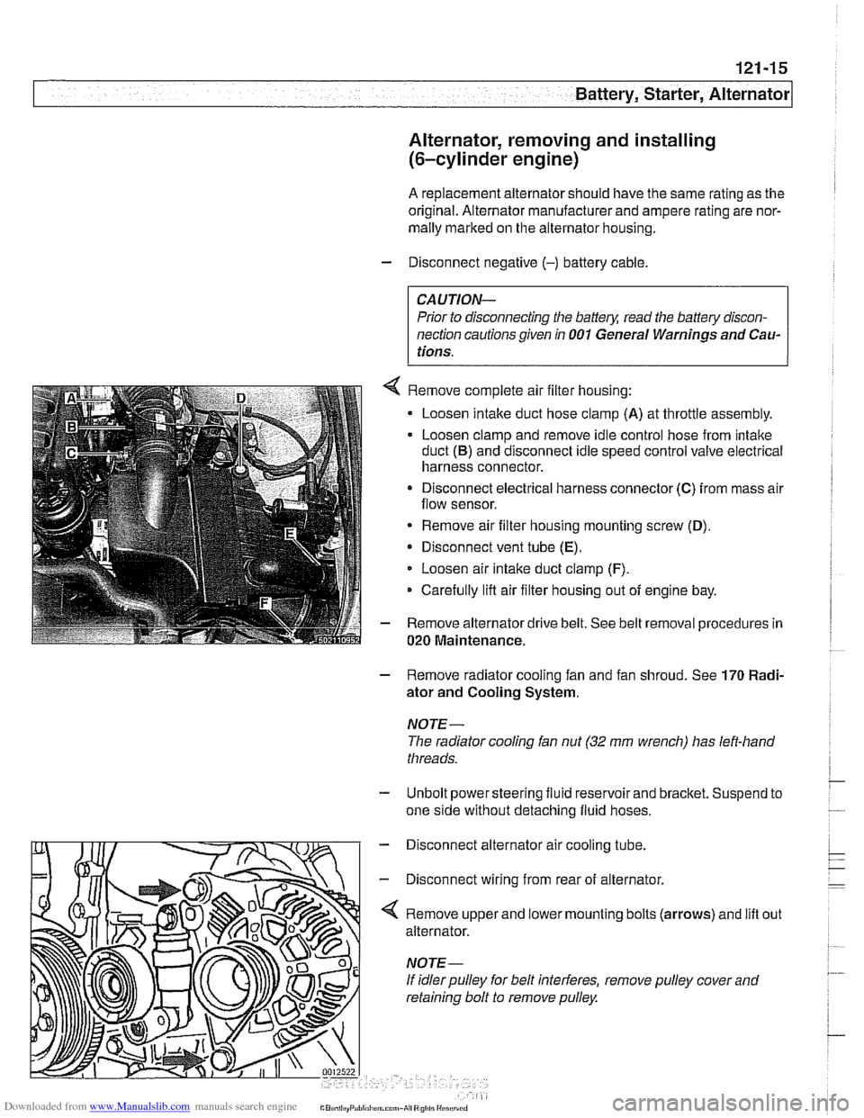
Remove complete air filter housing:
Loosen intake duct hose clamp
(A) at throttle assembly.
Loosen clamp and remove idle control hose from intake
duct
(B) and disconnect idle speed control valve electrical
harness connector.
Disconnect electrical harness connector
(C) from mass air
flow sensor.
* Remove air filter housing mounting screw (D),
Disconnect vent tube (E).
Loosen air intake duct clamp (F).
Carefully lifl air filter housing out of engine bay.
Remove alternator drive belt. See belt removal procedures in
020 Maintenance.
- Remove radiator cooling fan and fan shroud. See 170 Radi-
ator and Cooling System.
NOTE-
The radiator cooling fan nut (32 mm wrench) has left-hand
threads.
- Unbolt power steering fluid reservoir and bracket. Suspend to
one side without detaching fluid hoses.
- Disconnect alternator air cooling tube.
- Disconnect wiring from rear of alternator.
'4 Remove upper and lower mounting bolts (arrows) and lift
alternator.
If idler pulley for belt interferes, remove pulley cover and
retaining bolt to remove pulley. out
Page 386 of 1002

Downloaded from www.Manualslib.com manuals search engine
I Battery, Starter, Alternator
- Check for battery voltage at terminal 50 of starter motor with
key in start position. If voltage is not present, check wiring be-
tween ignition switch and starter terminal. Check the EWS
system and other inputs that disrupt terminal
56 to the start-
er. See ELE Electrical
Wiring Diagrams. If voltage is
present and no other visible wiring faults can be found, prob-
lem is most likely in starter motor.
Starter, removing and installing
(6-cylinder engine)
The starter is removed from below. Access to starter bolts is
difficult. Be sure to have the proper tools on hand before pro-
ceeding.
NOTE-
Access to the starter wiring is very limited. Forbetteraccess,
it may be necessary to remove the intake manifold.
- Disconnect negative (-) battery cable.
CAUTIOI\C
Prior to disconnecting the battern read the baltery discon-
nection cautions
in OOlGeneral Cautions and Warnings.
Remove complete air filter hous~ng:
Loosen intake duct hose clamp (A) at throttle assembly.
Loosen clamp and remove idle control hose from intake
duct
(B) and disconnect idle speed control valve electrical
harness connector.
Disconnect electrical harness connector
(C) from mass air
flow sensor.
Remove air filter housing mounting screw (D)
Disconnect vent tube
(E).
Loosen air intake duct clamp (F).
Carefully lift air filter housing out of engine bay.
Disconnect throttle cable.
Raise vehicle and support safely.
WARNING-
Make sure the car is stable and well supported at all times.
Use a professional automotive
lift orjack stands designed for
the purpose. A
floorjaclc is not adequate support
- Working underneath car, remove engine splash shield
- Disconnect fuel lines and harness connectors from retaining
brackets, as necessary.
Page 403 of 1002

Downloaded from www.Manualslib.com manuals search engine
130-1 3
Fuel Injection I
< Unplug harness connector (arrow) from sensor.
CAUTION-
Be sure ignition is OFF before disconnecting or reconnecting
DME system components.
NOTE-
Do not confuse the throttle position sensor on the main Nirot-
tle body with the throttle position switch on the secondary
throttle body, where applicable.
- Remove two mounting screws holding sensor to throttle
housing.
- Installation is reverse of removal. Clear adaptation settings
from ECM using BMW-compatible scan tool.
NOTE-
Poor idle quality may be noticeable for a period if the adapta-
tion settings are not cleared after installing new TPS.
ldle speed control valve,
checking and replacing
The idle speed control valve regulates idle speed by redirect-
inq airaround the throttlevalve.The idlespeed control valve is
mounted on the underside of the intake manifold adjacent to
the dipstick tube bracket. Accessing the valve is best accom-
plished by first removing the air filter housing and the throttle
body assembly.
The valve issupplied with
batteryvoltagefrom the ECM relay.
The idle speed control valve incorporates a two-coil rotary ac-
tuator. The ground sides of each coil are pulsed
sirnulta-
neously by the ECM. The duty cycle of each circuit is varied to
achieve the required idle speed.
Afaulty ldle speed control valve sets afault code and the MIL
is illuminated when
OED II fault criteria are exceeded.
Before checking the idle speed control valve, confirm that the
throttle position sensor is working correctly.
- With engine running, check that idle speed control valve is
buzzing.
- Turn on AIC system or shift transmission into drive. ldle
should remain steady or increase slightly.
Page 404 of 1002

Downloaded from www.Manualslib.com manuals search engine
Fuel Injection
- If idle speed valve is not buzzing, or if idle decreases when
AIC is turned on, stop engine and disconnect harness con-
nector from idle speed valve.
connector
CAUTION-
Be sure ignition is OFFbefore disconnecting or reconnecting
DME system components.
Checlc resistance of valve across valve terminals.
Idle speed control valve resistance
Terminals
1 and 2 20 i-2Q
Terminals 2 and 3 20 C2Q
Terminals 1 and 3 40 C4Q
The idle speed control valve is mounted under the intake
manifold. Accessing the valve is best accomplished by first
removing the air filter housing and the throttle housing.
< Disconnect intake air boot from throttle housing. Unbolt throt-
tle body and lay aside. Do not disconnect throttle cable or
electrical harness connectors to throttle body.
NOTE-
For additional worlcing room, unfasten and lift out the com.
plete air filter housing.
- Working under intake manifold, disconnect electrical harness
connector from idle speed control valve.
Unbolt dipstick tube
bracket (A) from intalte manifold.
- Remove two bolts (B) retaining idle speed control valve to un-
derside of intalte manifold. Remove valve from intalte mani-
fold. Remove hose clamp and disconnect hose.
- Installation is reverse of removal. Use new gaskets when in-
stalling.