Page 1 of 71
Servicing clutch mechanism Assembly overview - Pedal cluster (LHD vehicles) 1.Bracket ◆ Detach
steering
column from
steering box
before
removing
=> Running Gear, FWD and 4WD; Repair group 48; Removing and installing steering column
2.Pivot pin
◆ For clutch
pedal and
brake pedal
◆ Installation
position:
groove (arrow)
towards clutch
pedal
3.Retainer
4.Hexagon socket
head bolt - 25 Nm
5.Brake pedal
6.Clutch pedal ◆ Removing and installing=>Page 30-5
7.Pin
◆ Clip onto clutch
pedal
8.Retainer
9.Master cylinder
◆ Removing and installing=>Page 30-22
10.Hexagon socket-head bolt - 20Nm
11.Mounting
◆ Insert in
mounting
bracket with
over-centre
spring Page 1 of 35-Speed Manual Gearbox 01A 4WD4.3.2014vw-wi://rl/A.en-GB.4B-S-S01AA.wi::21141305.xml?xsl=2
Page 9 of 71
Servicing clutch mechanism Adjusting clutch pedal switch -F 194 ◆ USA vehicles only
‒ → Slightly loosen the two bolts -
arrows-.
‒ Have the second mechanic press the clutch pedal to the limit stop.
‒ Insert a feeler gauge -A-, set at
dimension -a- 3.2 ± 0.2 mm,
between contact surface of the
clutch pedal and switch plunger.
‒ Swivel switch -B- to stop towards
feeler gauge -A- and tighten the two
securing bolts -arrows- to 8 Nm. Page 1 of 15-Speed Manual Gearbox 01A 4WD4.3.2014vw-wi://rl/A.en-GB.4B-S-S01AA.wi::21141309.xml?xsl=2
Page 16 of 71

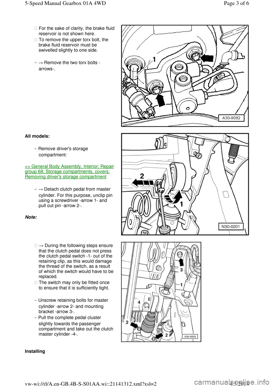
◆ For the sake of clarity, the brake fluid reservoir is not shown here.
◆ To remove the upper torx bolt, the
brake fluid reservoir must be
swivelled slightly to one side.
‒ → Remove the two torx bolts -
arrows-. All models: ‒ Remove driver's storage
compartment: => General Body Assembly, Interior; Repair group 68; Storage compartments, covers; Removing driver's storage compartment
‒ → Detach clutch pedal from master
cylinder. For this purpose, unclip pin
using a screwdriver -arrow 1- and
pull out pin -arrow 2-.
Note: ◆ → During the following steps ensure
that the clutch pedal does not press
the clutch pedal switch -1- out of the
retaining clip, as this would damage
the thread of the switch, as a result of which the switch would have to be replaced.
◆ The switch may only be fitted once
to ensure that it is sufficiently tight.
‒ Unscrew retaining bolts for master
cylinder -arrow 2- and mounting
bracket -arrow 3-.
‒ Pull the complete pedal cluster
slightly towards the passenger compartment and take out the clutch master cylinder -4-. Installing Page 3 of 65-Speed Manual Gearbox 01A 4WD4.3.2014vw-wi://rl/A.en-GB.4B-S-S01AA.wi::21141312.xml?xsl=2
Page 17 of 71
Installation is carried out in the reverse
order; note the following:
‒ → Insert the master cylinder so that
seal -1- and the washer lie behind
the mounting bracket and tighten
bolts -2- to 20 Nm.
‒ Press connection pipe -3- with guide
-arrow A- into recess -arrow B- on
mounting bracket. A second mechanic is required for the next
step.
‒ → Slide the complete pedal cluster
forwards towards the cross panel,
insert the bolt -arrow 3- and tighten it finger tight. The second mechanic should guide the pipe into the master cylinder starting from the plenum
chamber. Old version with internal torx socket-head bolts:
‒ → Tighten the retaining bolts for the
brake servo -arrows- to 25 Nm.
New version with external torx socket-
head bolts: ‒ → Tighten the retaining bolts for the Page 4 of 65-Speed Manual Gearbox 01A 4WD4.3.2014vw-wi://rl/A.en-GB.4B-S-S01AA.wi::21141312.xml?xsl=2
Page 29 of 71
2.Bolt for flywheel ◆ Always replace ◆ Vehicles
without dual
mass flywheel
60 Nm + turn
90° further
◆ With dual-
mass flywheel ‒ Screw length
22.5 mm
60 Nm + turn
90° further
‒ Screw length
43 mm
60 Nm + turn
180° further
3.Detach clutch plate
◆ Installation
position:
‒ Spring pack
(coil springs)
towards thrust
and gearbox
‒ Clutch lining
must make full Page 3 of 75-Speed Manual Gearbox 01A 4WD4.3.2014vw-wi://rl/A.en-GB.4B-S-S01AA.wi::21141315.xml?xsl=2
Page 30 of 71
contact with
flywheel
‒ Marking "Getriebeseite" (if present) must
face towards
thrust plate and
gearbox
◆ Do not grease
◆ Clutch plate diameter => from Page 00-3
◆ Centring =>Fig.1 ◆ Lightly grease
splines 4.Thrust plate ◆ Removing and
installing
=>Fig.1
◆ Check ends of
diaphragm
spring=> Fig.3 ◆ Checking
spring
connection
and riveted
fastenings =>
Fig.4
◆ Check wire
ring => Fig.5
5.Bolt - 25 Nm
◆ Loosen and
tighten
gradually in
several stages
working
diagonally
6.Needle bearing
◆ Check for
damage and
wear
◆ Removing and Page 4 of 75-Speed Manual Gearbox 01A 4WD4.3.2014vw-wi://rl/A.en-GB.4B-S-S01AA.wi::21141315.xml?xsl=2
Page 31 of 71
installing:
=> Relevant
engine
workshop
manual,
Mechanical
components;
Repair group
13 → Fig.1 Centring clutch plate and removing and installing thrust plate
‒ Loosen and tighten bolts gradually in
several stages working diagonally.
Tightening torque: 25 Nm.
‒ Reverse position of retainer 3067 when
removing.
‒ Installation position of clutch plate: spring
pack (coil springs) or marking
"Getriebeseite" towards pressure plate and
gearbox.
‒ Clutch lining and contact surface of
pressure plate must make full contact with
flywheel before securing bolts are inserted. ‒ Use mandrel 3176 to centre clutch plate.
→ Fig.2 Weight-optimised dual-mass flywheel
Identification: Cheese-head bolts -B- are
countersunk in the flywheel -A-. Page 5 of 75-Speed Manual Gearbox 01A 4WD4.3.2014vw-wi://rl/A.en-GB.4B-S-S01AA.wi::21141315.xml?xsl=2
Page 53 of 71
bolts do not protrude over the bottom
circumference of the clamps.
‒ Bolted connections point towards
the right → Fig.3 Individual parts of mounting for vehicles with manual gearbox
1 - Buffer
2 - Spacer pipe
3 - Washer
4 - Lug, right
5 - Disc
6 - Bolt - 25 Nm
7 - Spacer
8 - Lug, left
9 - Compression spring
10 - Bolt - 25 Nm
11 - Nut, self-tightening - 25 Nm
→ Fig.4 Individual parts of mounting for vehicles with automatic gearbox
1 - Disc
2 - Buffer
3 - Link
4 - Spacer
5 - Bolt - 25 Nm
6 - Bolt
7 - Disc
8 - Compression spring
9 - Spacer
10 - Nut, self-tightening - 25 Nm Page 6 of 64-cyl. Engine (5-valve, Turbo), Mechanical Components4.3.2014vw-wi://rl/A.en-GB.4B-MM-MMAEB.wi::20836882.xml?xsl=2