Page 1 of 16
26-29
Secondary air system, checking
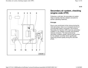
(engine code ATW) Following a cold start, the secondary air system
helps to quickly heat the catalytic converter for
quicker operating readiness.
Principle
Due to over-enrichment of the mixture during the
cold start phase, there is an increased amount of
uncombusted carbon monoxide in the exhaust.
Secondary Air Injection (AIR) improves secondary
oxidation in the catalytic converter and therefore
reduces emissions. The heat produced by
secondary oxidation greatly reduces start-up time
for the catalytic converter which significantly
improving exhaust quality during the cold start
phase.
Pa
ge 1 of 16 Secondar
y air s
ystem, checkin
g (en
gine code ATW
)
11/18/2002 htt
p://127.0.0.1:8080/audi/servlet/Dis
play?action=Goto&t
yp
e=re
pair&id=AUDI.B5.GE02.26.2
Page 2 of 16
26-30
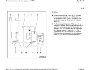
Function:
In the cold start phase, the ECM -2- activates
the secondary air pump -12- via the relay for
secondary air pump -1-. Air is supplied to the
combination valve for Secondary Air Injection
(AIR) -10-.
The Secondary Air Injection (AIR) valve -3- is
activated in parallel, which allows the vacuum to
reach the combination valve for Secondary Air
Injection (AIR) -10- and the vacuum diaphragm
for charge air pressure regulation -7-. The
combination valve for Secondary Air Injection
(AIR) thereby opens the path for secondary air
to the exhaust channels of the cylinder head.
Pa
ge 2 of 16 Secondar
y air s
ystem, checkin
g (en
gine code ATW
)
11/18/2002 htt
p://127.0.0.1:8080/audi/servlet/Dis
play?action=Goto&t
yp
e=re
pair&id=AUDI.B5.GE02.26.2
Page 3 of 16
26-31
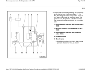
To prevent unnecessary heating, the secondary
air is diverted past the turbocharger -7-. For
this, the charge air pressureregulation pressure
unit opens the charge air pressure valve. The
pressure unit, designed as a double reservoir,
has a vacuum connection for this on the intake
side.
1 -
Secondary Air Injection (AIR) pump relay -
J299-
2 -
Motronic Engine Control Module (ECM) -
J220-
3 -
Secondary Air Injection (AIR) solenoid
valve -N112-
4 -
Intake manifold
5 -
Check valve
Installation position (light/dark side): Arrow
points in direction of flow, as shown
Pa
ge 3 of 16 Secondar
y air s
ystem, checkin
g (en
gine code ATW
)
11/18/2002 htt
p://127.0.0.1:8080/audi/servlet/Dis
play?action=Goto&t
yp
e=re
pair&id=AUDI.B5.GE02.26.2
Page 4 of 16
26-32
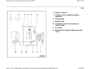
6 -
Vacuum reservoir
7 -
Pressure unit for charge air pressure
regulation
8 -
Turbocharger
9 -
Cylinder head
10 -
Combination valve for secondary air
injection (AIR)
11 -
Air cleaner
12 -
Secondary Air Injection (AIR) pump motor
-V101-
Pa
ge 4 of 16 Secondar
y air s
ystem, checkin
g (en
gine code ATW
)
11/18/2002 htt
p://127.0.0.1:8080/audi/servlet/Dis
play?action=Goto&t
yp
e=re
pair&id=AUDI.B5.GE02.26.2
Page 5 of 16
26-33
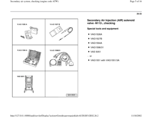
Secondary Air Injection (AIR) solenoid
valve -N112-, checking
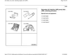
Special tools and equipment
VAG1526A
VAG1527B
VAG1594A
VAG1598/31
VAS 5051
- or
VAG1551 with VAG1551/3A
Pa
ge 5 of 16 Secondar
y air s
ystem, checkin
g (en
gine code ATW
)
11/18/2002 htt
p://127.0.0.1:8080/audi/servlet/Dis
play?action=Goto&t
yp
e=re
pair&id=AUDI.B5.GE02.26.2
Page 6 of 16
26-34
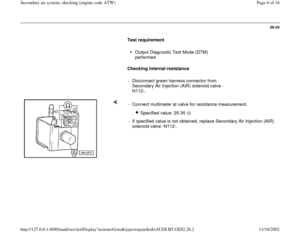
Test requirement
Output Diagnostic Test Mode (DTM)
performed
Checking internal resistance
- Disconnect green harness connector from
Secondary Air Injection (AIR) solenoid valve -
N112-.
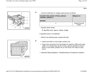
- Connect multimeter at valve for resistance measurement.
Specified value: 25-35
- If specified value is not obtained, replace Secondary Air Injection (AIR)
solenoid valve -N112-.
Pa
ge 6 of 16 Secondar
y air s
ystem, checkin
g (en
gine code ATW
)
11/18/2002 htt
p://127.0.0.1:8080/audi/servlet/Dis
play?action=Goto&t
yp
e=re
pair&id=AUDI.B5.GE02.26.2
Page 7 of 16
26-35
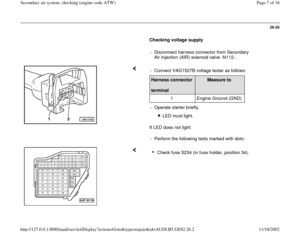
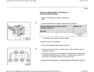
Checking voltage supply
- Disconnect harness connector from Secondary
Air Injection (AIR) solenoid valve -N112-.
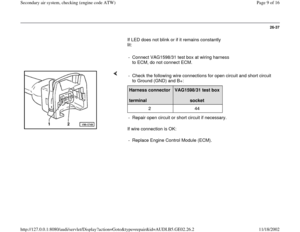
If LED does not light: - Connect VAG1527B voltage tester as follows:Harness connector
terminal
Measure to
1 Engine Ground (GND)
- Operate starter briefly.
LED must light.
- Perform the following tests marked with dots:
Check fuse S234 (in fuse holder, position 34).
Pa
ge 7 of 16 Secondar
y air s
ystem, checkin
g (en
gine code ATW
)
11/18/2002 htt
p://127.0.0.1:8080/audi/servlet/Dis
play?action=Goto&t
yp
e=re
pair&id=AUDI.B5.GE02.26.2
Page 8 of 16
26-36
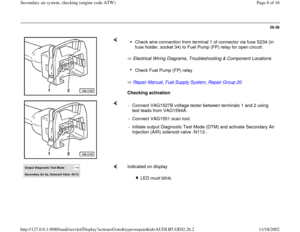
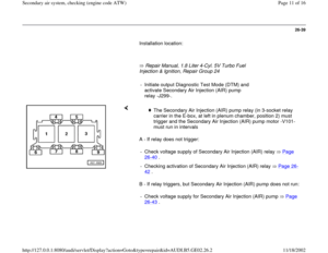
Electrical Wiring Diagrams, Troubleshooting & Component Locations
Repair Manual, Fuel Supply System, Repair Group 20
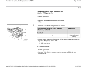
Checking activation
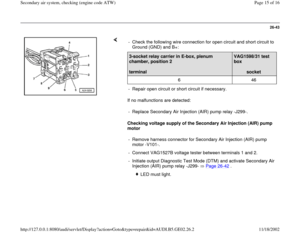
Check wire connection from terminal 1 of connector via fuse S234 (in
fuse holder, socket 34) to Fuel Pump (FP) relay for open circuit: Check Fuel Pump (FP) relay
- Connect VAG1527B voltage tester between terminals 1 and 2 using
test leads from VAG1594A.
- Connect VAG1551 scan tool.
- Initiate output Diagnostic Test Mode (DTM) and activate Secondary Air
Injection (AIR) solenoid valve -N112-.
Output Diagnostic Test Mode Secondary Air Inj. Solenoid Valve -N112
Indicated on display
LED must blink.
Pa
ge 8 of 16 Secondar
y air s
ystem, checkin
g (en
gine code ATW
)
11/18/2002 htt
p://127.0.0.1:8080/audi/servlet/Dis
play?action=Goto&t
yp
e=re
pair&id=AUDI.B5.GE02.26.2
 Following a cold start, the secondary air system
helps to quickly heat the catalytic converter for
quicker operating readiness.
Princip")


11 -
Air c")
 solenoid
valve -N112-, checking
Special tools and equipment
VAG1526A
VAG1527B
VAG1594A
VAG1598/31
VAS 5051
- or
VAG1551 with VAG1551/3A
Pa
ge 5 of")

performed
Checking internal resistance
- Disconnect green harness connector from
Secondary Air Injection (AIR)")
 solenoid valve -N112-.
If LED does not light: - Connect VAG1527B voltage tester")
