Page 9 of 34
01-8
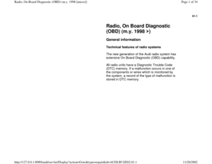
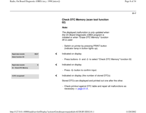
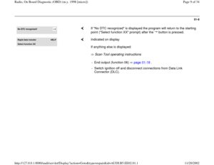
No DTC recognized!
If "No DTC recognized" is displayed the program will return to the starting
point ("Select function XX" prompt) after the button is pressed.
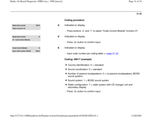
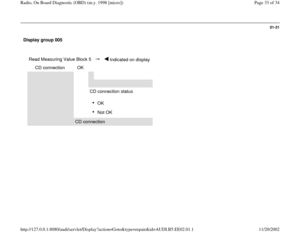
Rapid data transfer
HELP
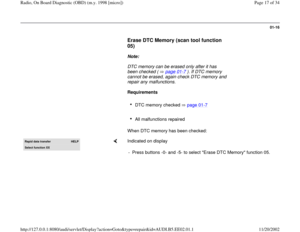
Select function XX
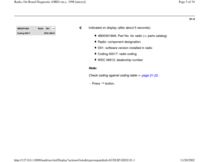
Indicated on display
If anything else is displayed:
Scan Tool operating instructions - End output (function 06) page 01
-18
.
- Switch ignition off and disconnect connections from Data Link
Connector (DLC).
Pa
ge 9 of 34 Radio, On Board Dia
gnostic
(OBD
) (m.
y. 1998 [micro]
)
11/20/2002 htt
p://127.0.0.1:8080/audi/servlet/Dis
play?action=Goto&t
yp
e=re
pair&id=AUDI.B5.EE02.01.1
Page 10 of 34
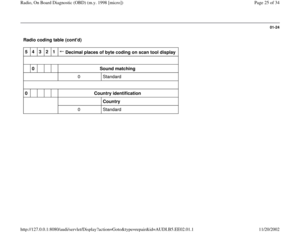
 table for radio system
Notes:
The following table lists all the malfunctions (stored as Diagnostic Trouble Codes, or DTCs) that can be recognized by the
radi")
01-9
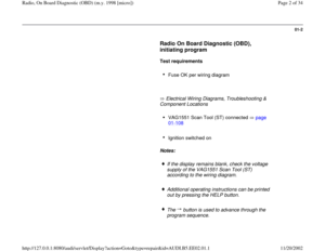
Diagnostic Trouble Code (DTC) table for radio system
Notes:
The following table lists all the malfunctions (stored as Diagnostic Trouble Codes, or DTCs) that can be recognized by the
radio system and printed out by the VAG1551 Scan Tool (ST). The DTCs are listed in order according to their 5-digit
numbers.
The DTCs only appear on the print-out from the scan tool.
Before replacing a component shown as faulty, check the wiring and connections to the component as well as Ground
(GND) connections according to the wiring diagram.
When a repair has been carried out, the DTC memory must always be checked again and then erased using the
VAG1551 scan tool.
Static and sporadic malfunctions are stored as DTCs in the DTC memory. If a malfunction occurs and persists for at least
2 seconds, it is identified as a static malfunction. If the malfunction does not occur again it is registered as a sporadic
malfunction and "/SP" will appear at the right of the display.
When the ignition is switched on, all existing malfunctions are automatically re-classified as sporadic malfunctions and will
only be registered as static malfunctions if they still occur after testing.
Sporadic malfunctions which no longer occur after 50 driving cycles (ignition on for at least 5 minutes, road speed of more
than 30 km/h or 19 mph) are erased automatically.
Pa
ge 10 of 34 Radio, On Board Dia
gnostic
(OBD
) (m.
y. 1998 [micro]
)
11/20/2002 htt
p://127.0.0.1:8080/audi/servlet/Dis
play?action=Goto&t
yp
e=re
pair&id=AUDI.B5.EE02.01.1
Page 11 of 34
01-10
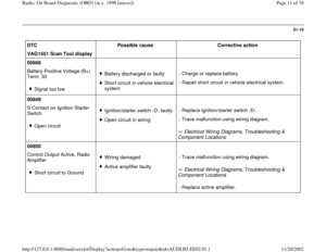
DTC
Possible cause
Corrective action
VAG1551 Scan Tool display
00668
Battery Positive Voltage (B+)
Term. 30
Signal too low
Battery discharged or faultyShort circuit in vehicle electrical
system - Charge or replace battery.
- Repair short circuit in vehicle electrical system.
00849
S Contact on Ignition Starter
Switch
Open circuit
Ignition/starter switch -D- faultyOpen circuit in wiring
Electrical Wiring Diagrams, Troubleshooting &
Component Locations - Replace ignition/starter switch -D-.
- Trace malfunction using wiring diagram.
00850
Control Output Active, Radio
Amplifier
Short circuit to Ground
Wiring damagedActive amplifier faulty
Electrical Wiring Diagrams, Troubleshooting &
Component Locations - Trace malfunction using wiring diagram.
- Replace active amplifier.
Pa
ge 11 of 34 Radio, On Board Dia
gnostic
(OBD
) (m.
y. 1998 [micro]
)
11/20/2002 htt
p://127.0.0.1:8080/audi/servlet/Dis
play?action=Goto&t
yp
e=re
pair&id=AUDI.B5.EE02.01.1
Page 12 of 34
01-11
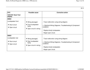
DTC
Possible cause
Corrective action
VAG1551 Scan Tool
display
00852
Loudspeaker front
Short circuit
Open circuit
Wiring damaged
Front loudspeaker
faulty
Open circuit in wiring Electrical Wiring Diagrams, Troubleshooting & Component
Locations - Trace malfunction using wiring diagram.
- Replace faulty loudspeaker.
- Repair open circuit.
00853
Loudspeaker rear
Short circuit
Open circuit
Wiring damaged
Rear loudspeaker
faulty
Open circuit in wiring Electrical Wiring Diagrams, Troubleshooting & Component
Locations - Trace malfunction using wiring diagram.
- Replace faulty loudspeaker.
- Repair open circuit.
Pa
ge 12 of 34 Radio, On Board Dia
gnostic
(OBD
) (m.
y. 1998 [micro]
)
11/20/2002 htt
p://127.0.0.1:8080/audi/servlet/Dis
play?action=Goto&t
yp
e=re
pair&id=AUDI.B5.EE02.01.1
Page 13 of 34
01-12
DTC
Possible cause
Corrective action
VAG1551 Scan Tool
display
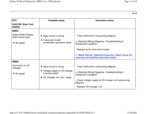
00854
Output Radio Display
Dash Panel Insert
No signal
Open circuit in wiring
Instrument cluster
combination processor faulty Electrical Wiring Diagrams, Troubleshooting &
Component Locations
Repair Manual, Electrical Equipment, Repair Group 90;
removing and installing instrument cluster
- Trace malfunction using wiring diagram.
- Replace faulty instrument cluster.
00855
Connection to CD
Changer
No signal
Open circuit in wiring
Voltage supply to CD changer
unit interrupted
CD changer unit -R41- faulty Electrical Wiring Diagrams, Troubleshooting &
Component Locations - Trace malfunction using wiring diagram.
- Check voltage supply to CD changer unit using wiring
diagram.
- Replace CD changer unit.
Pa
ge 13 of 34 Radio, On Board Dia
gnostic
(OBD
) (m.
y. 1998 [micro]
)
11/20/2002 htt
p://127.0.0.1:8080/audi/servlet/Dis
play?action=Goto&t
yp
e=re
pair&id=AUDI.B5.EE02.01.1
Page 14 of 34
01-13
DTC
Possible cause
Corrective action
VAG1551 Scan Tool
display
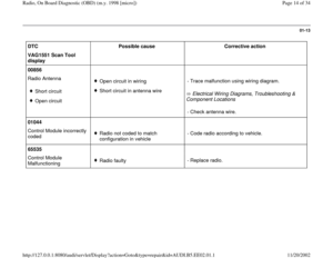
00856
Radio Antenna
Short circuit
Open circuit
Open circuit in wiring
Short circuit in antenna wire
Electrical Wiring Diagrams, Troubleshooting &
Component Locations - Trace malfunction using wiring diagram.
- Check antenna wire.
01044
Control Module incorrectly
coded
Radio not coded to match
configuration in vehicle - Code radio according to vehicle.
65535
Control Module
Malfunctioning Radio faulty- Replace radio.
Pa
ge 14 of 34 Radio, On Board Dia
gnostic
(OBD
) (m.
y. 1998 [micro]
)
11/20/2002 htt
p://127.0.0.1:8080/audi/servlet/Dis
play?action=Goto&t
yp
e=re
pair&id=AUDI.B5.EE02.01.1
Page 15 of 34
01-14
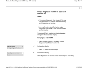
Output Diagnostic Test Mode (scan tool
function 03)
Notes:
The output Diagnostic Test Mode (DTM) may
only be carried out with the vehicle stationary
and the engine not running.
Any malfunctions identified by the output
Diagnostic Test Mode (DTM) must be traced
and eliminated.
The output DTM is used to test the loudspeaker
wiring and the secondary display.
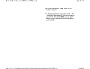
Carrying out output DTM
- Press buttons -0- and -3- to select "Output
Diagnostic Test Mode" function 03.
Rapid data transfer
Q
03 - Output Dia
gnostic Test Mode
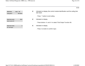
Indicated on display
- Press -Q- button to confirm input.
Output Diagnostic Test Mode Speaker
Indicated on display
All loudspeakers will receive a brief electrical pulse (inaudible).
Pa
ge 15 of 34 Radio, On Board Dia
gnostic
(OBD
) (m.
y. 1998 [micro]
)
11/20/2002 htt
p://127.0.0.1:8080/audi/servlet/Dis
play?action=Goto&t
yp
e=re
pair&id=AUDI.B5.EE02.01.1
Page 16 of 34
01-15
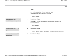
Note:
Any malfunctions (e.g. short circuits) that occur
will be recorded as DTCs in DTC memory.
-
Press button.Output Diagnostic Test Mode Outlet Radio displa
y instrument panel insert
Indicated on display
"DISPLAY ... TEST" will appear on the secondary display in the
instrument cluster.
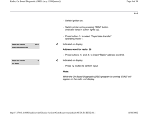
-
Press button.
Output Diagnostic Test Mode End
Indicated on display
-
Press button (returns scan tool to "Select function XX" prompt).
Rapid data transfer
HELP
Select function XX
Indicated on display
Pa
ge 16 of 34 Radio, On Board Dia
gnostic
(OBD
) (m.
y. 1998 [micro]
)
11/20/2002 htt
p://127.0.0.1:8080/audi/servlet/Dis
play?action=Goto&t
yp
e=re
pair&id=AUDI.B5.EE02.01.1
 after the button is pressed.
Rapid data transfer
H")

Term. 30
Signal too low
Battery discharged or faultyShort circuit")


Notes:
The output Diagnostic Test Mode (DTM) may
only be carried out with the vehicle stationary
and the engine not")
 that occur
will be recorded as DTCs in DTC memory.
-
Press button.Output Diagnostic Test Mode Outlet Radio displa
y instrumen")