Page 17 of 37
24-192
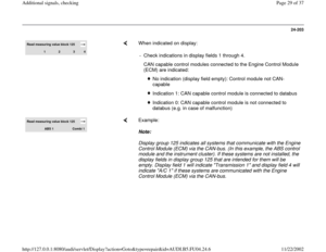
Display fields
1 2 3 4
Display Group 066: Signals to engine control module
Display xxx km/h
X X X X xxx km/h 0 0 0 0
Indicates Actual speed
Switch positions Specified speed Switch positions
Work
range
X0XX
X1XX
Specified value
X0XX
Clutch pedal not depressed
X1XX
Clutch pedal depressed
Note
Value:
X = insignificant
Pa
ge 17 of 37 Additional si
gnals, checkin
g
11/22/2002 htt
p://127.0.0.1:8080/audi/servlet/Dis
play?action=Goto&t
yp
e=re
pair&id=AUDI.B5.FU04.24.6
Page 18 of 37
24-193
If display does not appear as described:
Check switch
- Remove storage compartment on driver's
side.
Repair Manual, Body Interior, Repair Group
68
- Disconnect harness connector on clutch
switch.
- Connect hand-held multimeter for resistance
measurement between terminals 1 and 2.
Note:
The connector slots are marked on the back side
of the connector.
Specified value: approx.: 0
- Depress clutch pedal.
Specified value: (no continuity)
Pa
ge 18 of 37 Additional si
gnals, checkin
g
11/22/2002 htt
p://127.0.0.1:8080/audi/servlet/Dis
play?action=Goto&t
yp
e=re
pair&id=AUDI.B5.FU04.24.6
Page 19 of 37
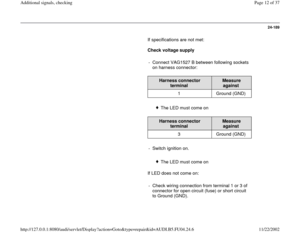
If specifications are not obtained:
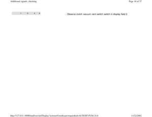
- Replace clutch vacuum vent valve switch.
Pa
ge 19 of 37 Additional si
gnals, checkin
g
11/22/2002 htt
p://127.0.0.1:8080/audi/servlet/Dis
play?action=Goto&t
yp
e=re
pair&id=AUDI.B5.FU04.24.6
Page 20 of 37
24-194
If specification is obtained:
Check voltage supply
- Connect VAG1527 B between following sockets
on harness connector:
Harness connector
terminal
Measure
against
2 Ground (GND)
- Switch ignition on.
The LED must come on
If LED does not come on:
- Check wire connection from terminal 2 of
connector for open circuit (fuse) or short circuit
to Ground (GND).
Electrical Wiring Diagrams, Troubleshooting &
Component Locations
- If necessary eliminate open circuit or short
circuit to Ground (GND)
Pa
ge 20 of 37 Additional si
gnals, checkin
g
11/22/2002 htt
p://127.0.0.1:8080/audi/servlet/Dis
play?action=Goto&t
yp
e=re
pair&id=AUDI.B5.FU04.24.6
Page 21 of 37
24-195
If LED comes on:
Check activation
- Connect VAG1598/31 test box to wiring harness
for engine control module. Do not connect to the
engine control module itself Page 24
-20
.
Test the following wiring connections for open
circuits and short to B+ or Ground (GND):
Harness
connector
terminal
VAG1598/31 test box,
socket
1 39
- Repair any open/short circuit as necessary.
Pa
ge 21 of 37 Additional si
gnals, checkin
g
11/22/2002 htt
p://127.0.0.1:8080/audi/servlet/Dis
play?action=Goto&t
yp
e=re
pair&id=AUDI.B5.FU04.24.6
Page 22 of 37
 receives the
crash signal (\"Crash shut-down activated\") from
the airbag control module.
If the airbag control mod")
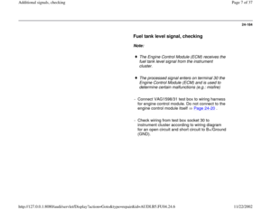
24-196
Crash signal, checking
The Engine Control Module (ECM) receives the
crash signal ("Crash shut-down activated") from
the airbag control module.
If the airbag control module sends the crash
signal to the ECM (if an accident occurred or if a
output Diagnostic Test Mode (DTM) was carried
out), the ECM shuts off the fuel pump, that
means the engine stalls, however, afterwards the
engine can be started again (e.g. when removing
the vehicle from the accident area)
The ECM cannot switch off the fuel pump during
an accident if the malfunction "Crash Signal from
Airbag Control Unit/Range Performance" from
the airbag control module is sent to ECM. The
engine control module cannot recognize the
crash signal from the airbag control module; e.g.:
if the wiring between the ECM and the airbag
control module is faulty.
- Connect VAG1598/31 test box to wiring harness
for engine control module. Do not connect to the
engine control module itself Page 24
-20
.
Pa
ge 22 of 37 Additional si
gnals, checkin
g
11/22/2002 htt
p://127.0.0.1:8080/audi/servlet/Dis
play?action=Goto&t
yp
e=re
pair&id=AUDI.B5.FU04.24.6
Page 23 of 37
24-197
Test the following wiring connections for open
circuit and/or short to B+ or Ground (GND) and
open circuit.
VAG1598/31 test
box, socket
Airbag control module,
contact
67 Electrical Wiring Diagrams,
Troubleshooting & Component
Locations
Resistance in wiring: max. 1.5 ohm
Eliminate open circuit or short circuit.
Electrical Wiring Diagrams, Troubleshooting &
Component Locations If no malfunctions are found in wiring: Check
DTC memory of airbag control module.
Pa
ge 23 of 37 Additional si
gnals, checkin
g
11/22/2002 htt
p://127.0.0.1:8080/audi/servlet/Dis
play?action=Goto&t
yp
e=re
pair&id=AUDI.B5.FU04.24.6
Page 24 of 37
24-198
Signal for rough road recognition from
ABS/EDL control module, checking
Note:
The ABS/EDL control module generates the
rough road signal if it recognizes wheel spin on
a wheel. The Engine Control Module (ECM)
switches off the misfire recognition once the
rough road signal is recognized by the ECM.
The rough road signal should only be checked if
the malfunction (P1606) 18014 "Rough Road
Spec Engine Torque ABS-ECU/Electrical
Malfunction" is stored in the DTC memory. It is
possible that the malfunction "Misfiring" is also
stored in DTC memory, however this is then a
sequence error and should be ignored.
The wiring and the rough road signal is
monitored by the ECM.
Pa
ge 24 of 37 Additional si
gnals, checkin
g
11/22/2002 htt
p://127.0.0.1:8080/audi/servlet/Dis
play?action=Goto&t
yp
e=re
pair&id=AUDI.B5.FU04.24.6


 and
open circuit.
VAG1598/31 test
box, socket
Airbag control module,
contact
67")
