Page 9 of 47

Test
step VAG1598
socket Test of
Test
conditions
- additional
steps Specified values
Corrective action
1.")
01-121
VAG1598/12 adapter cable Measuring range: Voltage measurement (20 V)
Test
step VAG1598
socket Test of
Test
conditions
- additional
steps Specified values
Corrective action
1.4 13 and
ground Terminal 30
at E87
Ignition off - approx. battery voltage - Repair voltage supply using
wiring diagram.
1.5 7 and
ground Terminal 58
at E87 Ignition on Parking
lights on - approx. battery voltage - Repair voltage supply using
wiring diagram.
1.6 7 and
ground Terminal 58
at E87 Ignition on Parking
lights on - less than 2 V - Rectify short circuit to positive
using wiring diagram.
1.7 45 and
ground Terminal 58D
at E87 Ignition on Parking
lights on - 0 to 12 V (depends on
setting of illumination
rheostat) - Determine and rectify open circuit
or short circuit using wiring
diagram.
1.8 45 and
ground Terminal 58D
at E87 Ignition on Parking
lights off - less than 2 V - Rectify short circuit to positive
using wiring diagram.
Pa
ge 9 of 47 A/C s
ystem, electrical testin
g
11/21/2002 htt
p://127.0.0.1:8080/audi/servlet/Dis
play?action=Goto&t
yp
e=re
pair&id=AUDI.B5.HA01.01.2
Page 10 of 47
01-122
Test No. 2 (temperature sensors G17, G56 and G89) VAG1598/11 adapter cable Measuring range: Resistance measurement (20 kohm)
Test
step VAG1598
socket Test of
Test conditions
- additional steps Specified values
Corrective action
2.1 48 + 52 Outside Air
Temperature
Sensor G17
Measure
temperature at
mounting location
of sensor - resistance table, page 01
-
123
(Resistance values
depend on measured
temperatures at mounting
location of sensor(s)
- Determine and rectify
short circuit, open circuit
in wiring or contact
resistance using wiring
diagram.
- Replace applicable
temperature sensor
page 87
-106
2.2 50 + 52 Instrument Panel
Interior
Temperature
Sensor G56
Measure
temperature at
mounting location
of sensor
2.3 47 + 52 Fresh Air Intake
Duct Temperature
Sensor G89 Measure
temperature at
mounting location
of sensor
Pa
ge 10 of 47 A/C s
ystem, electrical testin
g
11/21/2002 htt
p://127.0.0.1:8080/audi/servlet/Dis
play?action=Goto&t
yp
e=re
pair&id=AUDI.B5.HA01.01.2
Page 11 of 47
01-123
Temperature sensor resistances (based on ambient temperature, resistance in k ohm) Temperature measured at mounting
location of sensor Instrument Panel
Interior
Temperature
Sensor
-G56- Outside Air Temperature Sensor -G17- and Fresh Air
Intake Duct Temperature Sensor -G89-
-40 C (-40 F)
(100) (34.7)
-30 C (-22 F) (52.7) 18.1
-20 C (1 F) (28.6) 9.95
-10 C (14 F) 16.2 5.59
0 C (32 F) 9.40 3.28
5 C (41 F) 7.27 2.54
10 C (50 F) 5.66 1.99
15 C (59 F) 4.45 1.57
20 C (68 F) 3.50 1.25
25 C (77 F) 2.79 1.00
30 C (86 F) 2.23 0.80
35 C (95 F) 1.80 0.65
40 C (104 F) 1.45 0.53
50 C (122 F) 0.79 0.36
60 C (140 F) 0.67 0.25
Pa
ge 11 of 47 A/C s
ystem, electrical testin
g
11/21/2002 htt
p://127.0.0.1:8080/audi/servlet/Dis
play?action=Goto&t
yp
e=re
pair&id=AUDI.B5.HA01.01.2
Page 12 of 47
70 C (158 F)
0.47 -
80 C (176 F) 0.33 -
Pa
ge 12 of 47 A/C s
ystem, electrical testin
g
11/21/2002 htt
p://127.0.0.1:8080/audi/servlet/Dis
play?action=Goto&t
yp
e=re
pair&id=AUDI.B5.HA01.01.2
Page 13 of 47
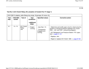
01-124
Test No. 3 (Fresh Air Blower V2 and Control module for fresh air blower J126) VAG1598/11 adapter cable Measuring range: Voltage measurement (20 V)
Test
step VAG1598
socket Test of
Test
conditions
- additional
steps Specified
values Corrective action
3.1 16 and
ground Control module
for fresh air
blower J126
Ignition
on - Voltage less
than 5 V
- Blower does
not run. - Determine and rectify short circuit to positive in
wiring/connections between J126 and -E87-
using wiring diagram.
- Replace J126
3.2 14 and
ground Voltage supply for
Fresh Air Blower
V2 Ignition
on - approx.
battery
voltage - Repair voltage supply using wiring diagram.
3.3 11 and
ground Voltage supply for
J126 (via V2) Ignition
on - approx.
battery
voltage
Pa
ge 13 of 47 A/C s
ystem, electrical testin
g
11/21/2002 htt
p://127.0.0.1:8080/audi/servlet/Dis
play?action=Goto&t
yp
e=re
pair&id=AUDI.B5.HA01.01.2
Page 14 of 47
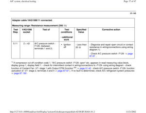
01-125
VAG1598/11 adapter cable
LED voltage tester US 1115
Test
step VAG1598
socket Test of
Test
conditions
- additional
steps Specified values
Corrective action
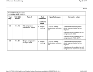
3.4 13 + 16 Control module for
fresh air blower -
J126-
Ignition
on - LED in voltage
tester comes on
- Fresh air blower
runs - Determine and rectify open circuit in
wiring/connections between -J126- and -
E87-.
- Check Fresh Air Blower V2
operates freely.
- Replace -J126-.
Pa
ge 14 of 47 A/C s
ystem, electrical testin
g
11/21/2002 htt
p://127.0.0.1:8080/audi/servlet/Dis
play?action=Goto&t
yp
e=re
pair&id=AUDI.B5.HA01.01.2
Page 15 of 47
 VAG1598/11 adapter cable Measuring range: Resistance measurement (20 kilo ohm)
Test
step VAG1598
socket")
01-126
Test No. 4 (air/temperature distribution flap motors and related potentiometers) VAG1598/11 adapter cable Measuring range: Resistance measurement (20 kilo ohm)
Test
step VAG1598
socket Test of
Test
conditions
- additional
steps Specified values
Corrective action
4.1 52 +
28
29
37
30 Potentiometer
(in flap motor)
-G92- (-V68-)
-G112- (-V70-
)
-G113- (-V71-
)
-G114- (-V85-
)
- greater than 0.1kW and less
than 5.7kW (depends on
position of flap motor) - Determine and rectify open circuit
in wiring, contact resistance or short
circuit using wiring diagram.
- Replace applicable flap motor
page 87
-106
.
4.2 8 +
28
29
37
30 Potentiometer
(in flap motor)
-G92- (-V68-)
-G112- (-V70-
)
-G113- (-V71-
)
-G114- (-V85-
)
- greater than 0.1kW and less
than 5.7kW (depends on
position of flap motor)
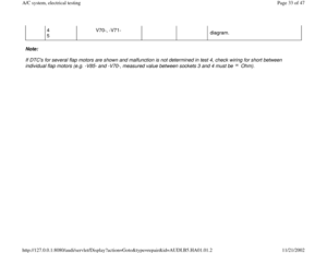
Notes:
Potentiometer resistance (Specified values: 3.6 k to 5.7 k between flap motor terminal 3 and 4) can only be measured
Pa
ge 15 of 47 A/C s
ystem, electrical testin
g
11/21/2002 htt
p://127.0.0.1:8080/audi/servlet/Dis
play?action=Goto&t
yp
e=re
pair&id=AUDI.B5.HA01.01.2
Page 16 of 47
directly at the flap motor (parallel circuit).
Potentiometers resistance (between flap motor terminal 3 and 5, plus 4 and 5) depends on the position of the flap motor.
Measure only with installed flap motor. The upper specified value is not achieved in test steps 4.1 and 4.2 (to achieve this
value, all connectors of the other flap motors would have to be unplugged during the measurement, parallel circuit).
If -E87- recognizes DTC" potentiometer short circuit to ground or open circuit/short circuit to positive", test all
potentiometers.
Pa
ge 16 of 47 A/C s
ystem, electrical testin
g
11/21/2002 htt
p://127.0.0.1:8080/audi/servlet/Dis
play?action=Goto&t
yp
e=re
pair&id=AUDI.B5.HA01.01.2


 VAG1598/11 adapter cable Measuring range: Resistance measurement (20 kohm)
Test
step VAG1598
socket Test of
Test conditions
- addit")
 Temperature measured at mounting
location of sensor Instrument Panel
Interior
Temperature
Sensor
-G56-")

0.47 -
80 C (176 F) 0.33 -
Pa
ge 12 of 47 A/C s
ystem, electrical testin
g
11/21/2002 htt
p://127.0.0.1:8080/audi/servlet/Dis
play?action=Goto&t
yp
e=re
pair&id=AUDI.B5.HA01.01")
 VAG1598/11 adapter cable Measuring range: Voltage measurement (20 V)
Test
step VAG1598
socket Test of
Tes")

.
Potentiometers resistance (between flap motor terminal 3 and 5, plus 4 and 5) depends on the position of the flap motor.
Measure only with installed f")