Page 11 of 656
0A-6 GENERAL INFORMATION
Identification Information
Vehicle Identification Number
The vehicle body number is on the left side of instrument panel
and punched on the chassis inside the tire housing on the right
front side.
Page 16 of 656

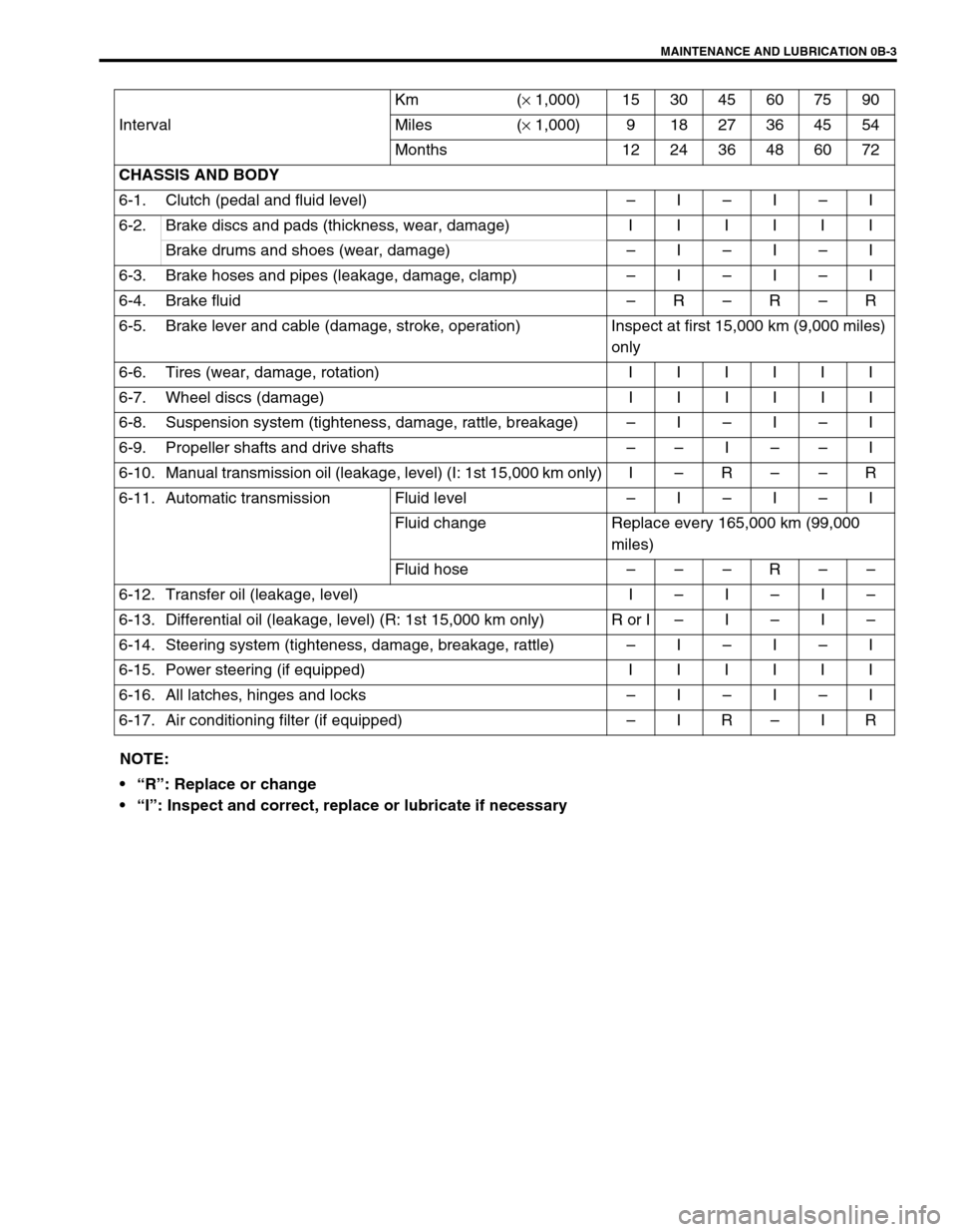
MAINTENANCE AND LUBRICATION 0B-3
IntervalKm (× 1,000) 153045607590
Miles (× 1,000) 9 18 27 36 45 54
Months 12 24 36 48 60 72
CHASSIS AND BODY
6-1. Clutch (pedal and fluid level)–I–I–I
6-2.Brake discs and pads (thickness, wear, damage) IIIIII
Brake drums and shoes (wear, damage)–I–I–I
6-3. Brake hoses and pipes (leakage, damage, clamp)–I–I–I
6-4. Brake fluid–R–R–R
6-5. Brake lever and cable (damage, stroke, operation) Inspect at first 15,000 km (9,000 miles)
only
6-6.Tires (wear, damage, rotation) IIIIII
6-7.Wheel discs (damage) IIIIII
6-8. Suspension system (tighteness, damage, rattle, breakage)–I–I–I
6-9. Propeller shafts and drive shafts––I––I
6-10. Manual transmission oil (leakage, level) (I: 1st 15,000 km only) I–R––R
6-11. Automatic transmission Fluid level –I–I–I
Fluid change Replace every 165,000 km (99,000
miles)
Fluid hose–––R––
6-12. Transfer oil (leakage, level) I–I–I–
6-13. Differential oil (leakage, level) (R: 1st 15,000 km only) R or I–I–I–
6-14. Steering system (tighteness, damage, breakage, rattle)–I–I–I
6-15.Power steering (if equipped) IIIIII
6-16. All latches, hinges and locks–I–I–I
6-17. Air conditioning filter (if equipped)–IR–IR
NOTE:
“R”: Replace or change
“I”: Inspect and correct, replace or lubricate if necessary
Page 88 of 656

FRONT SUSPENSION 3D-1
3D
SECTION 3D
FRONT SUSPENSION
CONTENTS
On-Vehicle Service......................................... 3D-1
Suspension Control Arm/Bushings .............. 3D-1Tightening Torque Specification .................. 3D-2
On-Vehicle Service
Suspension Control Arm/Bushings
INSTALLATION
For the details, refer to the same item of the same section in the
Service Manual mentioned in the FOREWORD of this manual
noting following point.
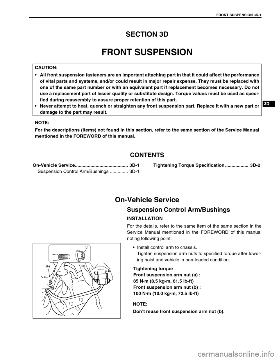
Install control arm to chassis.
Tighten suspension arm nuts to specified torque after lower-
ing hoist and vehicle in non-loaded condition.
Tightening torque
Front suspension arm nut (a) :
85 N·m (8.5 kg-m, 61.5 lb-ft)
Front suspension arm nut (b) :
100 N·m (10.0 kg-m, 72.5 lb-ft) CAUTION:
All front suspension fasteners are an important attaching part in that it could affect the performance
of vital parts and systems, and/or could result in major repair expense. They must be replaced with
one of the same part number or with an equivalent part if replacement becomes necessary. Do not
use a replacement part of lesser quality or substitute design. Torque values must be used as speci-
fied during reassembly to assure proper retention of this part.
Never attempt to heat, quench or straighten any front suspension part. Replace it with a new part or
damage to the part may result.
NOTE:
For the descriptions (items) not found in this section, refer to the same section of the Service Manual
mentioned in the FOREWORD of this manual.
NOTE:
Don’t reuse front suspension arm nut (b).
(b)
Page 120 of 656
PARKING AND REAR BRAKE 5C-3
On-Vehicle Service
Parking Brake CableBrake Drum
INSPECTION
Brake drum
Inspect drum for cleanliness. Check wear of its braking surface by
measuring its inside diameter.
Whenever brake drums are removed, they should be thoroughly
cleaned and inspected for cracks, scores, deep grooves.Brake dram inside diameter “a ”
S ta n dard : 2 54 mm (9.99 in .)
S erv ic e L im it : 2 56 m m ( 10.07 i n.)
1. Parking brake switch 6. Equalizer 11. Color ring 16. Crossmember 21. Parking brake cable nut
2. Parking brake lever 7. Pin 12. Cable 17. Chassis frame Tightening torque
3. Parking brake lever bolt 8. Equalizer 13. Grommet 18. Hanger
4. Floor 9. Adjust rod 14. Bolt 19. Rear axle
5. Locking nut 10. Coupler 15. Clamp (if equipped) 20. G-sensor (if equipped)
Page 315 of 656

6A2-28 ENGINE MECHANICAL (H27 ENGINE)
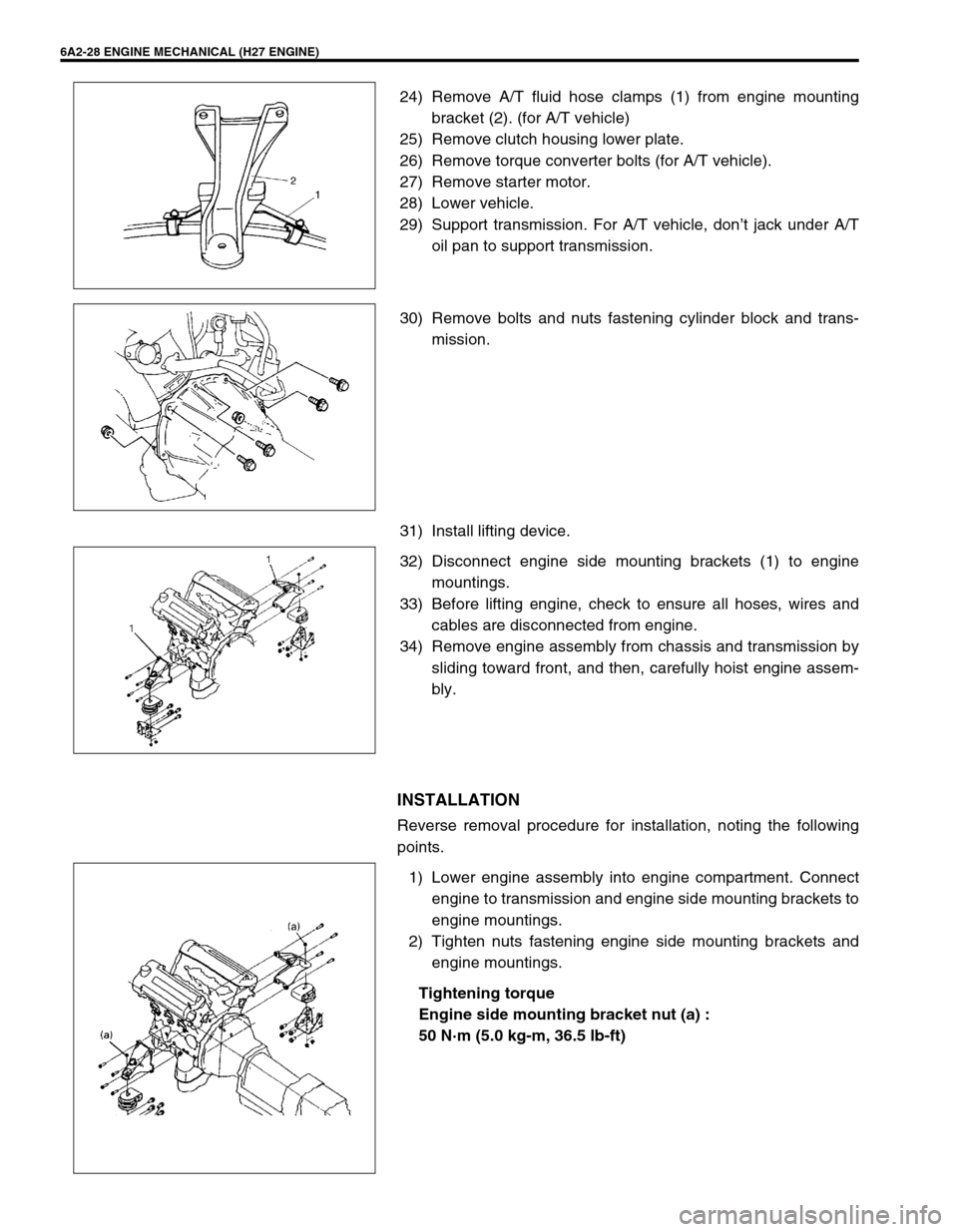
24) Remove A/T fluid hose clamps (1) from engine mounting
bracket (2). (for A/T vehicle)
25) Remove clutch housing lower plate.
26) Remove torque converter bolts (for A/T vehicle).
27) Remove starter motor.
28) Lower vehicle.
29) Support transmission. For A/T vehicle, don’t jack under A/T
oil pan to support transmission.
30) Remove bolts and nuts fastening cylinder block and trans-
mission.
31) Install lifting device.
32) Disconnect engine side mounting brackets (1) to engine
mountings.
33) Before lifting engine, check to ensure all hoses, wires and
cables are disconnected from engine.
34) Remove engine assembly from chassis and transmission by
sliding toward front, and then, carefully hoist engine assem-
bly.
INSTALLATION
Reverse removal procedure for installation, noting the following
points.
1) Lower engine assembly into engine compartment. Connect
engine to transmission and engine side mounting brackets to
engine mountings.
2) Tighten nuts fastening engine side mounting brackets and
engine mountings.
Tightening torque
Engine side mounting bracket nut (a) :
50 N·m (5.0 kg-m, 36.5 lb-ft)
Page 316 of 656

ENGINE MECHANICAL (H27 ENGINE) 6A2-29
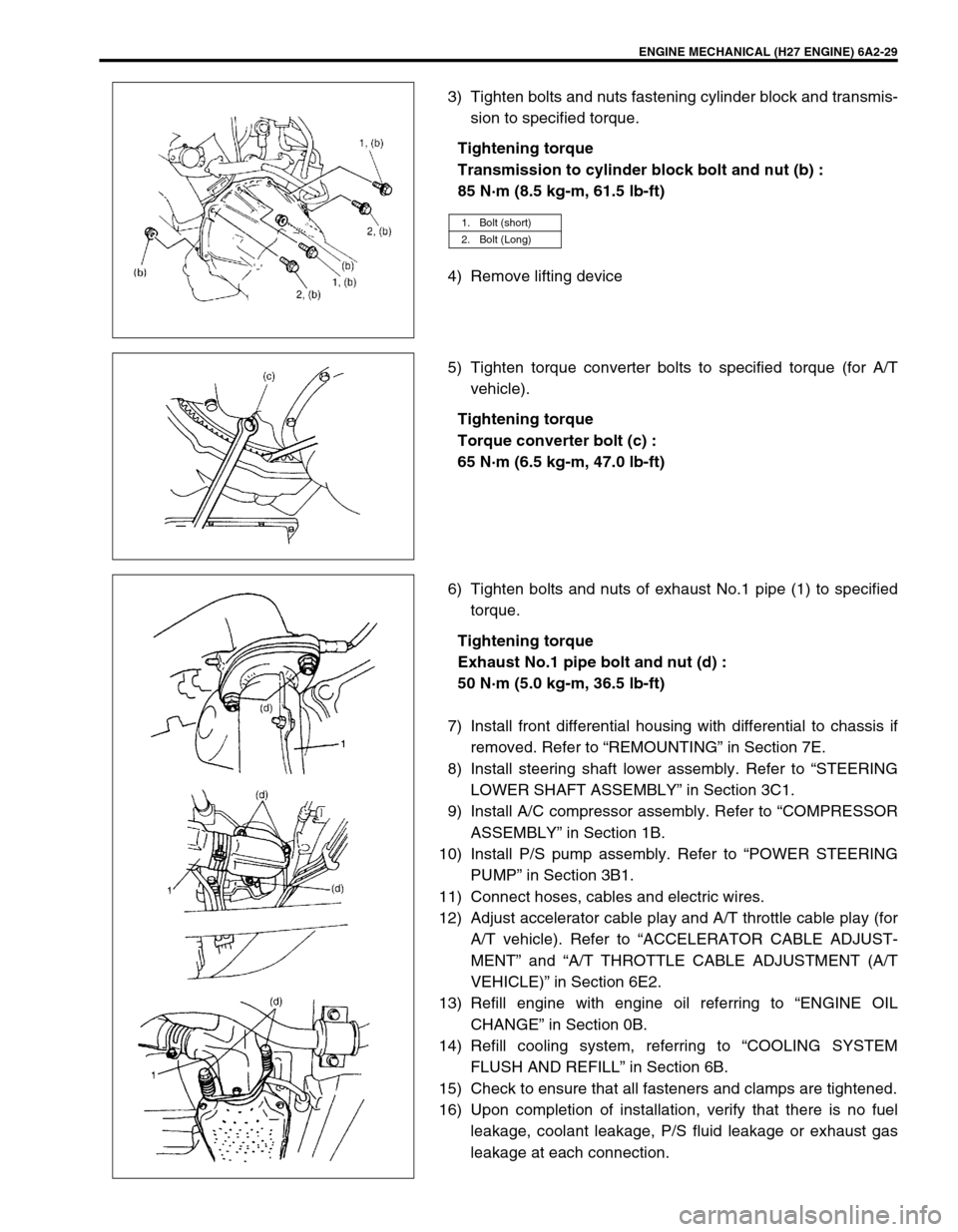
3) Tighten bolts and nuts fastening cylinder block and transmis-
sion to specified torque.
Tightening torque
Transmission to cylinder block bolt and nut (b) :
85 N·m (8.5 kg-m, 61.5 lb-ft)
4) Remove lifting device
5) Tighten torque converter bolts to specified torque (for A/T
vehicle).
Tightening torque
Torque converter bolt (c) :
65 N·m (6.5 kg-m, 47.0 lb-ft)
6) Tighten bolts and nuts of exhaust No.1 pipe (1) to specified
torque.
Tightening torque
Exhaust No.1 pipe bolt and nut (d) :
50 N·m (5.0 kg-m, 36.5 lb-ft)
7) Install front differential housing with differential to chassis if
removed. Refer to “REMOUNTING” in Section 7E.
8) Install steering shaft lower assembly. Refer to “STEERING
LOWER SHAFT ASSEMBLY” in Section 3C1.
9) Install A/C compressor assembly. Refer to “COMPRESSOR
ASSEMBLY” in Section 1B.
10) Install P/S pump assembly. Refer to “POWER STEERING
PUMP” in Section 3B1.
11) Connect hoses, cables and electric wires.
12) Adjust accelerator cable play and A/T throttle cable play (for
A/T vehicle). Refer to “ACCELERATOR CABLE ADJUST-
MENT” and “A/T THROTTLE CABLE ADJUSTMENT (A/T
VEHICLE)” in Section 6E2.
13) Refill engine with engine oil referring to “ENGINE OIL
CHANGE” in Section 0B.
14) Refill cooling system, referring to “COOLING SYSTEM
FLUSH AND REFILL” in Section 6B.
15) Check to ensure that all fasteners and clamps are tightened.
16) Upon completion of installation, verify that there is no fuel
leakage, coolant leakage, P/S fluid leakage or exhaust gas
leakage at each connection.
1. Bolt (short)
2. Bolt (Long)