Page 348 of 656

ENGINE AND EMISSION CONTROL SYSTEM (SEQUENTIAL MULTIPORT FUEL INJECTION FOR H27 ENGINE) 6E2-15
Idle Speed/Idle Air Control (IAC) Duty Inspec-
tion
Before idle speed/IAC duty check, make sure of the following.
•Lead wires and hoses of engine/emission control systems
are connected securely.
•Accelerator cable is adjusted.
•Ignition timing is within specification.
•All accessories (wipers, heater, lights, A/C, etc.) are out of
service.
•Air cleaner has been properly installed and is in good condi-
tion.
•ECM (PCM) does not detect any malfunction DTC.
After above items are all confirmed, check idle speed and IAC
duty as follows.
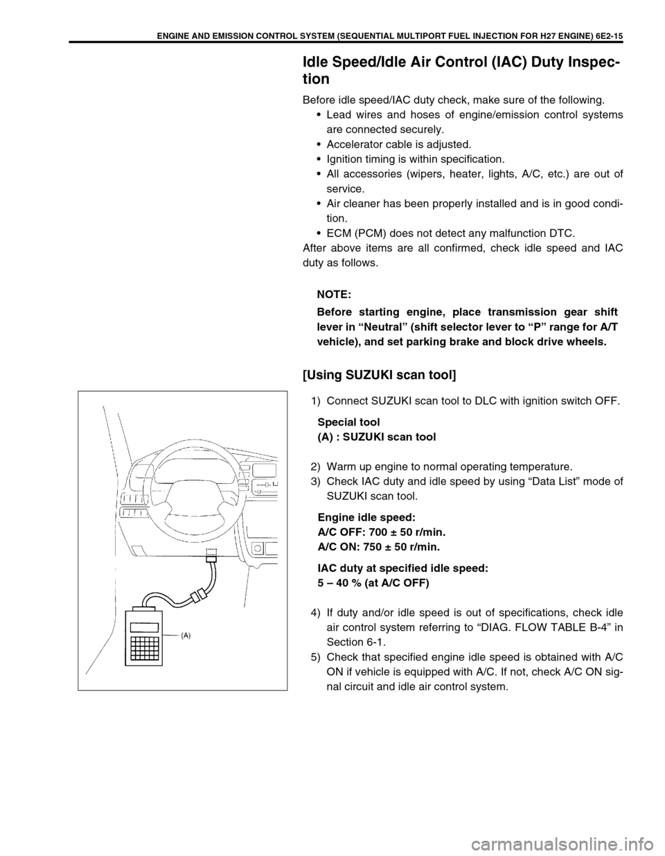
[Using SUZUKI scan tool]
1) Connect SUZUKI scan tool to DLC with ignition switch OFF.
Special tool
(A) : SUZUKI scan tool
2) Warm up engine to normal operating temperature.
3) Check IAC duty and idle speed by using “Data List” mode of
SUZUKI scan tool.
Engine idle speed:
A/C OFF: 700 ± 50 r/min.
A/C ON: 750 ± 50 r/min.
IAC duty at specified idle speed:
5 – 40 % (at A/C OFF)
4) If duty and/or idle speed is out of specifications, check idle
air control system referring to “DIAG. FLOW TABLE B-4” in
Section 6-1.
5) Check that specified engine idle speed is obtained with A/C
ON if vehicle is equipped with A/C. If not, check A/C ON sig-
nal circuit and idle air control system. NOTE:
Before starting engine, place transmission gear shift
lever in “Neutral” (shift selector lever to “P” range for A/T
vehicle), and set parking brake and block drive wheels.
Page 371 of 656

6E2-38 ENGINE AND EMISSION CONTROL SYSTEM (SEQUENTIAL MULTIPORT FUEL INJECTION FOR H27 ENGINE)
HEATER INSPECTION
1) Disconnect HO2S-1 or -2 coupler.
2) Using ohmmeter, measure resistance between terminals
“VB” and “GND” of HO2S coupler (1).
If found faulty, replace HO2S.
Resistance of HO2S heater:
11.7 – 14.3 Ω
ΩΩ Ω (at 20 °C (68 °F)) for HO2S-2
5.0 – 6.4 Ω
ΩΩ Ω (at 20 °C (68 °F)) for HO2S-1
3) Connect HO2S coupler securely.
Heated oxygen sensor (sensor 2)
REMOVAL
1) Disconnect negative (–) cable from battery.
2) Disconnect coupler (3) of oxygen sensor(s).
3) Remove oxygen sensor(s) (2) from exhaust manifold(s) (1).
INSTALLATION
Reverse removal procedure noting the followings.
•Tighten oxygen sensor(s) to specified torque.
Tightening torque
Heated oxygen sensor 2 (a) : 45 N·m (4.5 kg-m, 32.5 lb-ft)
•Connect connector of oxygen sensor(s) and clamp wire har-
ness securely.
•After installing oxygen sensor(s), start engine and check that
no exhaust gas leakage exists. NOTE:
Temperature of HO2S affects resistance value largely.
Make sure that HO2S heater is at correct temperature.
WARNING:
To avoid danger of being burned, do not touch exhaust
system when system is hot. Oxygen sensor removal
should be performed when system is cool.
NOTE:
Be careful not to expose it to excessive shock.
Page 372 of 656

ENGINE AND EMISSION CONTROL SYSTEM (SEQUENTIAL MULTIPORT FUEL INJECTION FOR H27 ENGINE) 6E2-39
HEATER INSPECTION
Refer to “HEATED OXYGEN SENSOR (SENSOR 1) HEATER
INSPECTION”
Vehicle speed sensor (VSS)
ON-VEHICLE INSPECTION
1) Hoist vehicle.
2) Release parking brake lever, set transmission in neutral and
transfer in “2H”.
3) Remove ECM (PCM) cover.
4) Connector voltmeter between VSS terminal C51-3-1 of ECM
(PCM) connector and body ground.
5) Turn ignition switch ON and turn rear right tire slowly with
rear left tire locked.
Voltmeter should indicate deflection between 0 – 1 V and 8 –
14 V a few times while tire (1) is turned one revolution.
If check result is not satisfactory, proceed to flow table of
“DTC P0500” in Section 6-1.
REMOVAL, INSPECTION AND INSTALLATION
Refer to “VSS Removal, Inspection or Installation” in Section 7D.
Manifold absolute pressure sensor
REMOVAL
1) Disconnect negative (–) cable at battery.
2) Disconnect connector from manifold absolute pressure sen-
sor.
3) Remove manifold absolute pressure sensor from intake
manifold.
[A]: Terminal arrangement of ECM (PCM) coupler
(viewed from harness side)
1. VSS