1999 SUZUKI GRAND VITARA heater
[x] Cancel search: heaterPage 37 of 656

1B-12 AIR CONDITIONING (OPTIONAL)
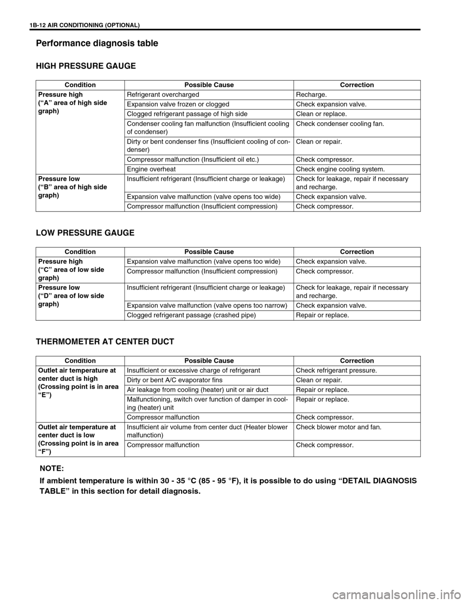
Performance diagnosis table
HIGH PRESSURE GAUGE
LOW PRESSURE GAUGE
THERMOMETER AT CENTER DUCT
Condition Possible Cause Correction
Pressure high
(“A” area of high side
graph)Refrigerant overcharged Recharge.
Expansion valve frozen or clogged Check expansion valve.
Clogged refrigerant passage of high side Clean or replace.
Condenser cooling fan malfunction (Insufficient cooling
of condenser)Check condenser cooling fan.
Dirty or bent condenser fins (Insufficient cooling of con-
denser)Clean or repair.
Compressor malfunction (Insufficient oil etc.) Check compressor.
Engine overheat Check engine cooling system.
Pressure low
(“B” area of high side
graph)Insufficient refrigerant (Insufficient charge or leakage) Check for leakage, repair if necessary
and recharge.
Expansion valve malfunction (valve opens too wide) Check expansion valve.
Compressor malfunction (Insufficient compression) Check compressor.
Condition Possible Cause Correction
Pressure high
(“C” area of low side
graph)Expansion valve malfunction (valve opens too wide) Check expansion valve.
Compressor malfunction (Insufficient compression) Check compressor.
Pressure low
(“D” area of low side
graph)Insufficient refrigerant (Insufficient charge or leakage) Check for leakage, repair if necessary
and recharge.
Expansion valve malfunction (valve opens too narrow) Check expansion valve.
Clogged refrigerant passage (crashed pipe) Repair or replace.
Condition Possible Cause Correction
Outlet air temperature at
center duct is high
(Crossing point is in area
“E”)Insufficient or excessive charge of refrigerant Check refrigerant pressure.
Dirty or bent A/C evaporator fins Clean or repair.
Air leakage from cooling (heater) unit or air duct Repair or replace.
Malfunctioning, switch over function of damper in cool-
ing (heater) unitRepair or replace.
Compressor malfunction Check compressor.
Outlet air temperature at
center duct is low
(Crossing point is in area
“F”)Insufficient air volume from center duct (Heater blower
malfunction)Check blower motor and fan.
Compressor malfunction Check compressor.
NOTE:
If ambient temperature is within 30 - 35 °C (85 - 95 °F), it is possible to do using “DETAIL DIAGNOSIS
TABLE” in this section for detail diagnosis.
Page 39 of 656

1B-14 AIR CONDITIONING (OPTIONAL)
Wiring Circuit
ACG
LT GRN
PNK
PNK
BLKORN
BLK
YEL/GRNRED/BLKBLK/WHT
BLU/WHTPNK/BLK
PNK/GRN
RED/BLK
WHT/RED
YEL/GRN
YEL/BLU
A/C
RED/BLU
RED/BLU
RED/BLKBLK
BLU/ORN
BLU/WHT
BLU/WHT
PNK
PNK/BLU
BLK
PNK/WHT
YEL/BLK
GRY/WHT
GRN/BLK
BLK/WHT
RED/BLK
YEL/GRN
BLK
BLK
BLK
YEL/BLK
YEL/GRN
YEL/GRNBLU/GRN
BLU/YELBLUBLU/BLK
BLU/BLK
17
21
22 18
16
15
19
2026 25 24 23
14
12
29
3
4
7
33 30
31
32
28
27
1213
10
11
35 349
856
A
1. Front blower motor main relay 10. Compressor relay 19. Battery 28. Solenoid valve relay
2. Front blower motor 11. Compressor 20. Generator 29. Rear blower motor relay
3. Front blower motor resistor 12. Condenser cooling fan motor
relay21. Ignition main fuse 60 A 30. Rear blower motor resistor
4. Front blower motor switch 13. Condenser cooling fan motor 22. Heater/A/C main fuse 60 A 31. Rear blower motor
5. A/C controller 14. Fuse box 23.“IG METER” fuse 20 A 32. Rear blower motor switch
6. ECM (PCM) 15.“A/C” fuse 25 A 24.“REAR DEFG” fuse 25 A 33. Rear A/C main switch
7. Heater mode control switch 16. Ignition switch 25.“REAR BLOW” fuse 20A 34. Rear A/C evaporator temperature con-
troller
8. Dual (refrigerant) pressure switch 17. Main fuse box 26.“FRONT BLOW” fuse 30A 35. Rear A/C evaporator temperature sensor
9. A/C evaporator thermistor
(A/C evaporator temperature sensor)18. Battery main fuse 100 A 27. Solenoid valve [A] : Rear A/C wiring circuit (if equipped)
Page 163 of 656

6-1-2 ENGINE GENERAL INFORMATION AND DIAGNOSIS (H27 ENGINE)
Table A-4 Malfunction Indicator Lamp
Check – MIL Does Not Flash or Just
Remains ON Even with Grounding
Diagnosis Switch Terminal (Vehicle with
Monitor Connector) ................................... 6-1-45
Table A-5 ECM (PCM) Power and Ground
Circuit Check – MIL Doesn’t Light at
Ignition Switch ON and Engine Doesn’t
Start Though It Is Cranked Up .................. 6-1-46
DTC P0100 (DTC No.33, 34) Mass Air
Flow Circuit Malfunction ............................ 6-1-48
DTC P0110 (DTC No.23, 25) Intake Air
Temp. (IAT) Circuit Malfunction ................ 6-1-50
DTC P0115 (DTC No.14, 15) Engine
Coolant Temp. Circuit Malfunction ............ 6-1-52
DTC P0120 (DTC No.21, 22) Throttle
Position Circuit Malfunction....................... 6-1-54
DTC P0121 Throttle Position Circuit
Range/Performance Problem ................... 6-1-56
DTC P0130 (DTC No.13) HO2S-1 (Bank 1)
Circuit Malfunction or No Activity
Detected.................................................... 6-1-58
DTC P0133 HO2S-1 (Bank 1) Circuit Slow
Response .................................................. 6-1-60
DTC P0135 HO2S-1 (Bank 1) Heater
Circuit Malfunction .................................... 6-1-61
DTC P0136 HO2S-2 (Bank 1) Circuit
Malfunction................................................ 6-1-63
DTC P0141 HO2S-2 (Bank 1) Heater
Circuit Malfunction .................................... 6-1-65
DTC P0150 (DTC No.26) HO2S-1 (Bank 2)
Circuit Malfunction or No Activity
Detected.................................................... 6-1-67
DTC P0153 HO2S-1 (Bank 2) Circuit Slow
Response .................................................. 6-1-69
DTC P0155 HO2S-1 (Bank 2) Heater
Circuit Malfunction .................................... 6-1-70
DTC P0156 HO2S-2 (Bank 2) Circuit
Malfunction................................................ 6-1-72
DTC P0161 HO2S-2 (Bank 2) Heater
Circuit Malfunction .................................... 6-1-74
DTC P0171/P0172 Fuel System Too
Lean/Rich (Bank 1) ................................... 6-1-76
DTC P0174/P0175 Fuel System Too
Lean/Rich (Bank 2) ................................... 6-1-78
DTC P0300/P0301/P0302/P0303/P0304/
P0305/P0306 Random Misfire/Cylinder 1
Misfire/Cylinder 2 Misfire/Cylinder 3 Misfire/
Cylinder 4 Misfire Detected/Cylinder 5
Misfire Detected/Cylinder 6 Misfire
Detected.................................................... 6-1-80
DTC P0325 (DTC No.43) Knock Sensor Circuit Malfunction ..................................... 6-1-82
DTC P0335 Crankshaft Position Sensor
Circuit Malfunction ..................................... 6-1-84
DTC P0340 (DTC No.42) Camshaft
Position Sensor Circuit Malfunction ........... 6-1-86
DTC P0400 Exhaust Gas Recirculation
Flow Malfunction ........................................ 6-1-89
DTC P0403 (DTC No.51) Exhaust Gas
Recirculation Circuit Malfunction ............... 6-1-92
DTC P0420 Catalyst System Efficiency
Below Threshold (Bank 1) ......................... 6-1-94
DTC P0430 Catalyst System Efficiency
Below Threshold (Bank 2) ......................... 6-1-96
DTC P0443 Evap Control System Purge
Control Valve Circuit Malfunction............... 6-1-98
Evap canister purge system
inspection ............................................. 6-1-100
Vacuum passage inspection ................ 6-1-100
Vacuum hose inspection ...................... 6-1-101
Evap canister purge valve and its
circuit inspection .................................. 6-1-101
Evap canister purge valve inspection .. 6-1-101
DTC P0460 Fuel Level Sensor Circuit
High Input ................................................ 6-1-103
DTC P0500 (DTC No.24) Vehicle Speed
Sensor Malfunction .................................. 6-1-105
DTC P0505 Idle Air Control System
Malfunction .............................................. 6-1-108
DTC P0601 (DTC No.71) Internal Control
Module Memory Check Sum Error .......... 6-1-110
DTC P1408 Manifold Absolute Pressure
Sensor Circuit Malfunction ....................... 6-1-111
DTC P1450/P1451 Barometric Pressure
Sensor Circuit Malfunction/Performance
Problem ................................................... 6-1-113
DTC P1500 Engine Starter Signal Circuit
Malfunction .............................................. 6-1-114
DTC P1510 Ecm Back-Up Power Supply
Malfunction .............................................. 6-1-115
Table B-1 Fuel Pump Circuit Inspection .. 6-1-116
Table B-2 Fuel Injectors and Circuit
Inspection ................................................ 6-1-117
Table B-3 Fuel Pressure Inspection ........ 6-1-119
Table B-4 Idle Air Control System
Inspection ................................................ 6-1-121
Table B-5 A/C Signal Circuits Inspection
(If Equipped) ............................................ 6-1-123
Table B-6 A/C Condenser Fan Motor
Relay Control System Inspection
(If Equipped) ............................................ 6-1-124
Special Tool ............................................... 6-1-125
Page 180 of 656

ENGINE GENERAL INFORMATION AND DIAGNOSIS (H27 ENGINE) 6-1-19
P0133HO2S circuit slow response
(Bank 1 - Sensor 1)Response time of HO2S-1 output volt-
age between rich and lean is longer
than specification.2 driving
cyclesNot
applicable
P0135HO2S heater circuit malfunc-
tion (Bank 1 - Sensor 1)Terminal voltage is lower than specifi-
cation at heater OFF or it is higher at
heater ON.2 driving
cyclesNot
applicable
P0136HO2S circuit malfunction
(Bank 1 - Sensor 2)Max. voltage of HO2S-2 is lower than
specification or its min. voltage is
higher than specification.2 driving
cyclesNot
applicable
P0141HO2S heater circuit malfunc-
tion (Bank 1 - Sensor 2)Terminal voltage is lower than specifi-
cation at heater OFF or it is higher at
heater ON.2 driving
cyclesNot
applicable
*P0150HO2S circuit malfunction
(Bank 2 - sensor 1)Min. output voltage of HO2S-1 is
higher than specification.
2 driving
cyclesNot
applicable Min. output voltage of HO2S-1 is
lower than specification.
Output voltage of HO2S-1 fails to go
above specification.
**P0150
(No.26)HO2S (Bank 2 - Sensor 1) no
activity detectedOutput voltage of HO2S-1 fails to go
above specification (or HO2S-1 cir-
cuit open).2 driving
cycles2 driving
cycles
P0153HO2S circuit slow response
(Bank 2 - Sensor 1)Response time HO2S-1 output volt-
age between rich and lean is longer
than specification.2 driving
cyclesNot
applicable
P0155HO2S heater circuit malfunc-
tion (Bank 2 - Sensor 1)Terminal voltage i lower than specifi-
cation at heater OFF or it is higher at
heater ON.2 driving
cyclesNot
applicable
P0156HO2S circuit malfunction
(Bank 2 - Sensor 2)Max. voltage of HO2S-2 is lower than
specification or its min. voltage is
higher than specification.2 driving
cyclesNot
applicable
P0161HO2S heater circuit malfunc-
tion (Bank 2 - Sensor 2)Terminal voltage is lower than specifi-
cation at heater OFF or it is higher at
heater ON (or heater circuit or short).2 driving
cyclesNot
applicable
P0171 Fuel system too lean (Bank 1)Short term fuel trim or total fuel trim
(short and long terms added) is larger
than specification for specified time or
longer. (Fuel trim toward rich side is
large.)2 driving
cyclesNot
applicable
P0172 Fuel system too rich (Bank 1)Short term fuel trim or total fuel trim
(short and long terms added) is
smaller than specification for specified
time or longer. (Fuel trim toward lean
side is large.)2 driving
cyclesNot
applicable DTC NO. DETECTED ITEMDETECTING CONDITION
(DTC will set when detecting : )MIL
(vehicle
without
monitor
connector)MIL
(vehicle
with
monitor
connector)
Page 198 of 656

ENGINE GENERAL INFORMATION AND DIAGNOSIS (H27 ENGINE) 6-1-37
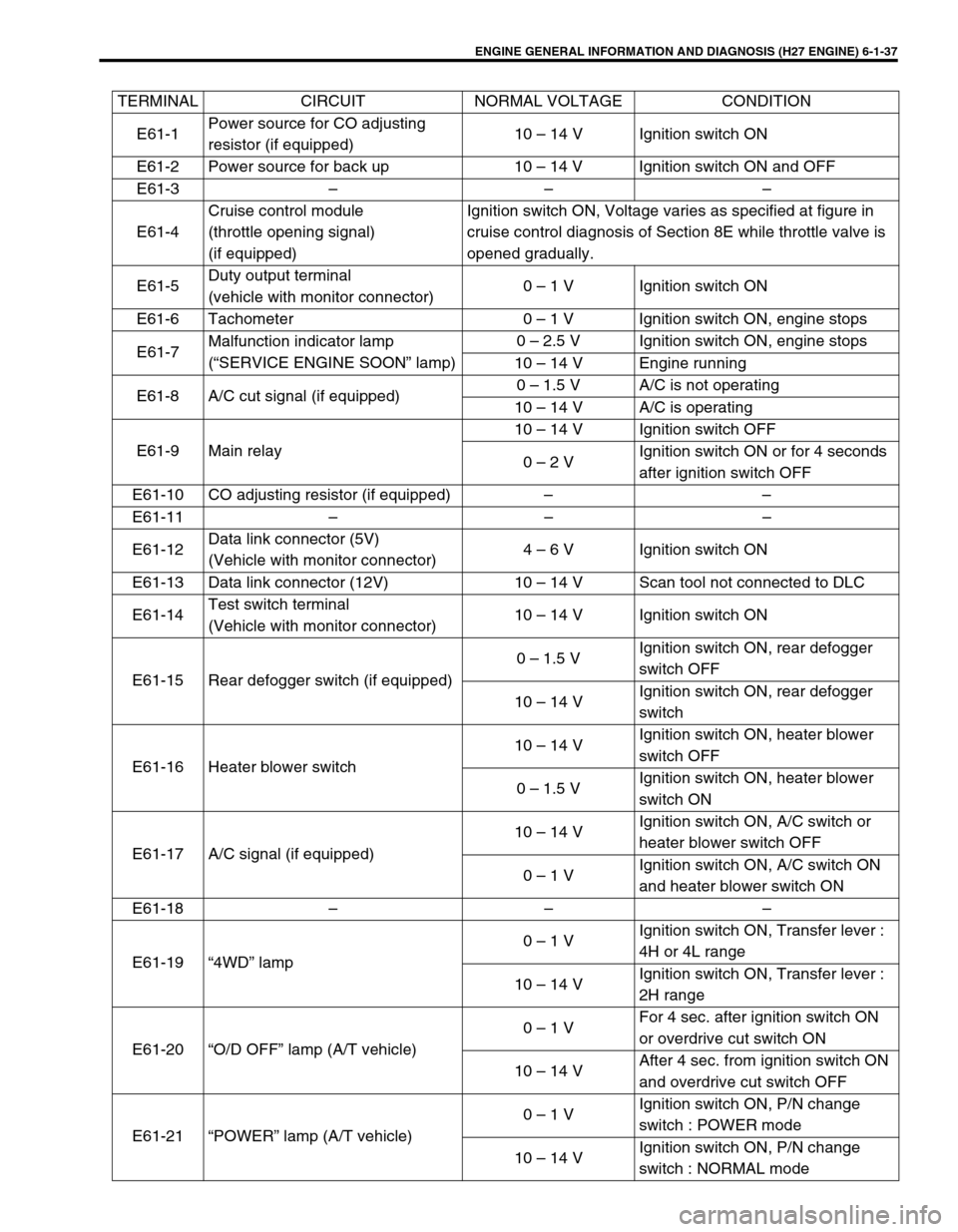
TERMINAL CIRCUIT NORMAL VOLTAGE CONDITION
E61-1Power source for CO adjusting
resistor (if equipped)10 – 14 V Ignition switch ON
E61-2 Power source for back up 10 – 14 V Ignition switch ON and OFF
E61-3 – – –
E61-4Cruise control module
(throttle opening signal)
(if equipped)Ignition switch ON, Voltage varies as specified at figure in
cruise control diagnosis of Section 8E while throttle valve is
opened gradually.
E61-5Duty output terminal
(vehicle with monitor connector)0 – 1 V Ignition switch ON
E61-6 Tachometer 0 – 1 V Ignition switch ON, engine stops
E61-7Malfunction indicator lamp
(“SERVICE ENGINE SOON” lamp)0 – 2.5 V Ignition switch ON, engine stops
10 – 14 V Engine running
E61-8 A/C cut signal (if equipped)0 – 1.5 V A/C is not operating
10 – 14 V A/C is operating
E61-9 Main relay10 – 14 V Ignition switch OFF
0 – 2 VIgnition switch ON or for 4 seconds
after ignition switch OFF
E61-10 CO adjusting resistor (if equipped) – –
E61-11 – – –
E61-12Data link connector (5V)
(Vehicle with monitor connector)4 – 6 V Ignition switch ON
E61-13 Data link connector (12V) 10 – 14 V Scan tool not connected to DLC
E61-14Test switch terminal
(Vehicle with monitor connector)10 – 14 V Ignition switch ON
E61-15 Rear defogger switch (if equipped)0 – 1.5 VIgnition switch ON, rear defogger
switch OFF
10 – 14 VIgnition switch ON, rear defogger
switch
E61-16 Heater blower switch10 – 14 VIgnition switch ON, heater blower
switch OFF
0 – 1.5 VIgnition switch ON, heater blower
switch ON
E61-17 A/C signal (if equipped)10 – 14 VIgnition switch ON, A/C switch or
heater blower switch OFF
0 – 1 VIgnition switch ON, A/C switch ON
and heater blower switch ON
E61-18 – – –
E61-19 “4WD” lamp0 – 1 VIgnition switch ON, Transfer lever :
4H or 4L range
10 – 14 VIgnition switch ON, Transfer lever :
2H range
E61-20 “O/D OFF” lamp (A/T vehicle)0 – 1 VFor 4 sec. after ignition switch ON
or overdrive cut switch ON
10 – 14 VAfter 4 sec. from ignition switch ON
and overdrive cut switch OFF
E61-21 “POWER” lamp (A/T vehicle)0 – 1 VIgnition switch ON, P/N change
switch : POWER mode
10 – 14 VIgnition switch ON, P/N change
switch : NORMAL mode
Page 202 of 656

ENGINE GENERAL INFORMATION AND DIAGNOSIS (H27 ENGINE) 6-1-41
C51-2-1 Fuel injector No.2
10 – 14 V Ignition switch ON
C51-2-2 Fuel injector No.1
C51-2-3 – – –
C51-2-4Heater of HO2S-1 (bank 1)
(if equipped)10 – 14 V Ignition switch ON
0 – 2 VAt specified idle speed after engine
warmed up
C51-2-5Heater of HO2S-1 (bank 2)
(if equipped)10 – 14 V Ignition switch ON
0 – 2 VAt specified idle speed after engine
warmed up
C51-2-6 – – –
C51-2-7 Ground – –
C51-2-8 Fuel injector No.4
10 – 14 V Ignition switch ON
C51-2-9 Fuel injector No.3
C51-2-10 – – –
C51-2-11 – – –
C51-2-12EGR valve (stepper motor coil 4)
(if equipped)0 – 1 V
Ignition switch ON C51-2-13EGR valve (stepper motor coil 3)
(if equipped)10 – 14 V
C51-2-14EGR valve (stepper motor coil 2)
(if equipped)10 – 14 V
C51-2-15EGR valve (stepper motor coil 1)
(if equipped)0 – 1 V
C51-2-16Heater of HO2S-2 (bank 1)
(if equipped)10 – 14 V Ignition switch ON
0 – 1 VAt specified idle speed after engine
warmed up
C51-2-17Heater of HO2S-2 (bank 2)
(if equipped)10 – 14 V Ignition switch ON
0 – 1 VAt specified idle speed after engine
warmed up
C51-2-18 – – –
C51-2-19Crankshaft position sensor (+)
(if equipped)––
C51-2-20Crankshaft position sensor (–)
(if equipped)––
C51-2-21 Fuel injector No.6
10 – 14 V Ignition switch ON
C51-2-22 Fuel injector No.5
C51-2-23 Ignition coil assembly for No.6 – –
C51-2-24 Ignition coil assembly for No.5 – –
C51-2-25 Ignition coil assembly for No.4 – –
C51-2-26 Ignition coil assembly for No.3 – –
C51-2-27 Ignition coil assembly for No.2 – –
C51-2-28 Ignition coil assembly for No.1 – –
C51-2-29 – – –
C51-2-30Ground for CKP sensor shield wire
(if equipped)–– TERMINAL CIRCUIT NORMAL VOLTAGE CONDITION
Page 203 of 656

6-1-42 ENGINE GENERAL INFORMATION AND DIAGNOSIS (H27 ENGINE)
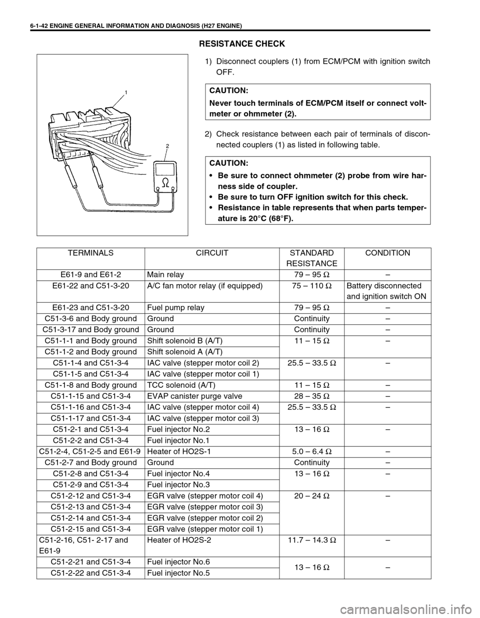
RESISTANCE CHECK
1) Disconnect couplers (1) from ECM/PCM with ignition switch
OFF.
2) Check resistance between each pair of terminals of discon-
nected couplers (1) as listed in following table. CAUTION:
Never touch terminals of ECM/PCM itself or connect volt-
meter or ohmmeter (2).
CAUTION:
Be sure to connect ohmmeter (2) probe from wire har-
ness side of coupler.
Be sure to turn OFF ignition switch for this check.
Resistance in table represents that when parts temper-
ature is 20°C (68°F).
TERMINALS CIRCUIT STANDARD
RESISTANCECONDITION
E61-9 and E61-2 Main relay 79 – 95 Ω–
E61-22 and C51-3-20 A/C fan motor relay (if equipped) 75 – 110 ΩBattery disconnected
and ignition switch ON
E61-23 and C51-3-20 Fuel pump relay 79 – 95 Ω–
C51-3-6 and Body ground Ground Continuity –
C51-3-17 and Body ground Ground Continuity –
C51-1-1 and Body ground Shift solenoid B (A/T) 11 – 15 Ω–
C51-1-2 and Body ground Shift solenoid A (A/T)
C51-1-4 and C51-3-4 IAC valve (stepper motor coil 2) 25.5 – 33.5 Ω–
C51-1-5 and C51-3-4 IAC valve (stepper motor coil 1)
C51-1-8 and Body ground TCC solenoid (A/T) 11 – 15 Ω–
C51-1-15 and C51-3-4 EVAP canister purge valve 28 – 35 Ω–
C51-1-16 and C51-3-4 IAC valve (stepper motor coil 4) 25.5 – 33.5 Ω–
C51-1-17 and C51-3-4 IAC valve (stepper motor coil 3)
C51-2-1 and C51-3-4 Fuel injector No.2 13 – 16 Ω–
C51-2-2 and C51-3-4 Fuel injector No.1
C51-2-4, C51-2-5 and E61-9 Heater of HO2S-1 5.0 – 6.4 Ω–
C51-2-7 and Body ground Ground Continuity –
C51-2-8 and C51-3-4 Fuel injector No.4 13 – 16 Ω–
C51-2-9 and C51-3-4 Fuel injector No.3
C51-2-12 and C51-3-4 EGR valve (stepper motor coil 4) 20 – 24 Ω–
C51-2-13 and C51-3-4 EGR valve (stepper motor coil 3)
C51-2-14 and C51-3-4 EGR valve (stepper motor coil 2)
C51-2-15 and C51-3-4 EGR valve (stepper motor coil 1)
C51-2-16, C51- 2-17 and
E61-9Heater of HO2S-2 11.7 – 14.3 Ω–
C51-2-21 and C51-3-4 Fuel injector No.6
13 – 16 Ω–
C51-2-22 and C51-3-4 Fuel injector No.5
Page 219 of 656

6-1-58 ENGINE GENERAL INFORMATION AND DIAGNOSIS (H27 ENGINE)
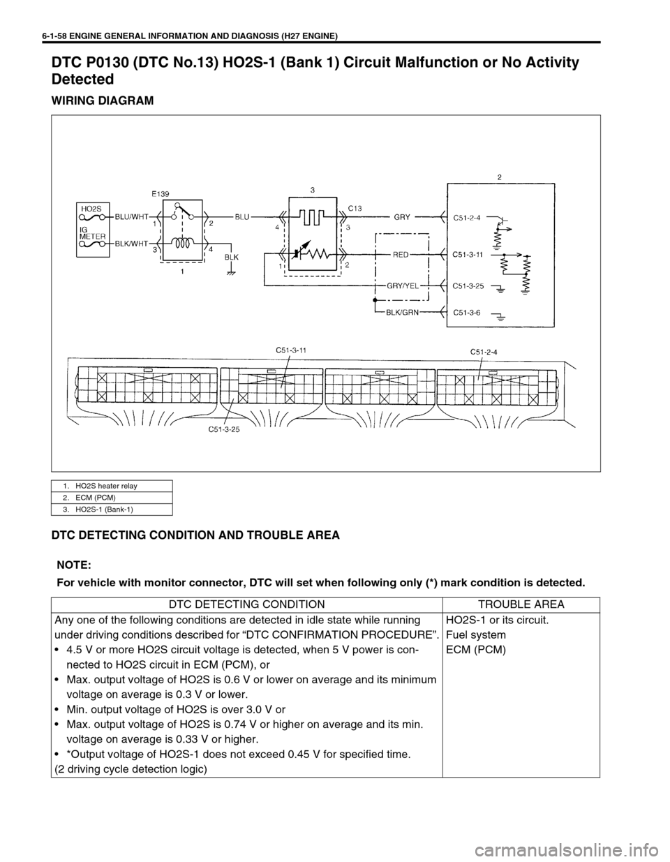
DTC P0130 (DTC No.13) HO2S-1 (Bank 1) Circuit Malfunction or No Activity
Detected
WIRING DIAGRAM
DTC DETECTING CONDITION AND TROUBLE AREA
1. HO2S heater relay
2. ECM (PCM)
3. HO2S-1 (Bank-1)
NOTE:
For vehicle with monitor connector, DTC will set when following only (*) mark condition is detected.
DTC DETECTING CONDITION TROUBLE AREA
Any one of the following conditions are detected in idle state while running
under driving conditions described for “DTC CONFIRMATION PROCEDURE”.
• 4.5 V or more HO2S circuit voltage is detected, when 5 V power is con-
nected to HO2S circuit in ECM (PCM), or
• Max. output voltage of HO2S is 0.6 V or lower on average and its minimum
voltage on average is 0.3 V or lower.
• Min. output voltage of HO2S is over 3.0 V or
• Max. output voltage of HO2S is 0.74 V or higher on average and its min.
voltage on average is 0.33 V or higher.
• *Output voltage of HO2S-1 does not exceed 0.45 V for specified time.
(2 driving cycle detection logic)HO2S-1 or its circuit.
Fuel system
ECM (PCM)