Page 403 of 656

6H-6 CHARGING SYSTEM
Specifications
Battery
Generator
Tightening Torque Specification
Battery type 55D23L 75D23L 95D26L
Rated capacity AH/5HR, 12 Volts 48 52 66
Electrolyte L (US/Imp.pt) 3.9 (8.24/6.86) 3.9 (8.24/6.86) 4.0 (8.53/7.04)
Electrolyte S.G. 1.28 when fully charged at 20°C (68°F)
Type 105 A type
Rated voltage 12 V
Nominal output 105 A
Permissible max. speed 18000 r/min.
No-load speed 1150 r/min (rpm)
Setting voltage 14.2 to 14.8 V
Permissible ambient temperature–30 to 90 °C (–22 to 194 °F)
Polarity Negative ground
Rotation Clockwise viewed from pulley side
Fastening partTightening torque
Nm kg-m lb-ft
Body ground bolt 8 0.8 6.0
Generator mounting bolts and nut 23 2.3 16.5
“B” terminal inner nut 3.6 0.37 3.0
“B” terminal outer nut 8 0.8 6.0
Generator pulley nut 111 11.2 81.5
Rear end frame nuts 4.5 0.45 3.5
Rear end cover nuts 4.5 0.45 3.5
Stator stud bolts 9.8 1.0 7.0
Drive end bearing plate screws 3.0 0.30 2.2
Rectifier screws 3.0 0.30 2.2
Regulator and brush holder screws 2.0 0.20 1.5
Terminal plate bolt 3.9 0.39 3.0
Page 611 of 656
10B-34 AIR BAG SYSTEM
DIAGNOSTIC FLOW TABLE
DTC B1031 :
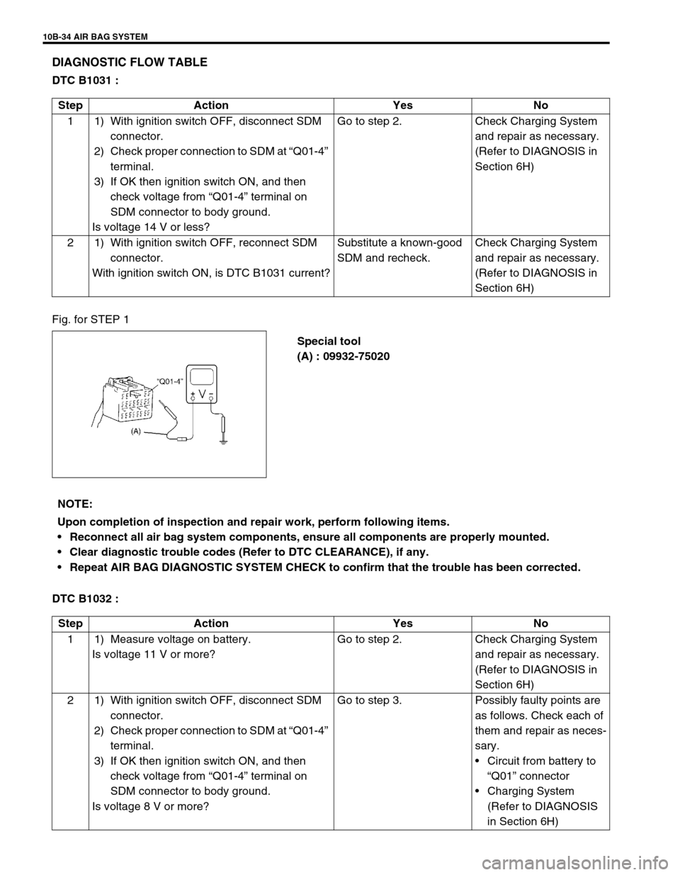
Fig. for STEP 1
Special tool
(A) : 09932-75020
DTC B1032 :Step Action Yes No
1 1) With ignition switch OFF, disconnect SDM
connector.
2) Check proper connection to SDM at “Q01-4”
terminal.
3) If OK then ignition switch ON, and then
check voltage from “Q01-4” terminal on
SDM connector to body ground.
Is voltage 14 V or less?Go to step 2. Check Charging System
and repair as necessary.
(Refer to DIAGNOSIS in
Section 6H)
2 1) With ignition switch OFF, reconnect SDM
connector.
With ignition switch ON, is DTC B1031 current?Substitute a known-good
SDM and recheck.Check Charging System
and repair as necessary.
(Refer to DIAGNOSIS in
Section 6H)
NOTE:
Upon completion of inspection and repair work, perform following items.
Reconnect all air bag system components, ensure all components are properly mounted.
Clear diagnostic trouble codes (Refer to DTC CLEARANCE), if any.
Repeat AIR BAG DIAGNOSTIC SYSTEM CHECK to confirm that the trouble has been corrected.
Step Action Yes No
1 1) Measure voltage on battery.
Is voltage 11 V or more?Go to step 2. Check Charging System
and repair as necessary.
(Refer to DIAGNOSIS in
Section 6H)
2 1) With ignition switch OFF, disconnect SDM
connector.
2) Check proper connection to SDM at “Q01-4”
terminal.
3) If OK then ignition switch ON, and then
check voltage from “Q01-4” terminal on
SDM connector to body ground.
Is voltage 8 V or more?Go to step 3. Possibly faulty points are
as follows. Check each of
them and repair as neces-
sary.
•Circuit from battery to
“Q01” connector
•Charging System
(Refer to DIAGNOSIS
in Section 6H)
Page 612 of 656
AIR BAG SYSTEM 10B-35
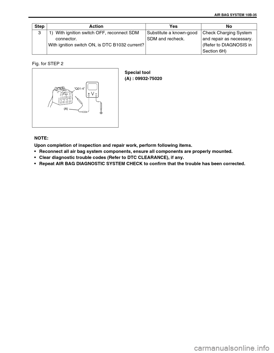
Fig. for STEP 2
Special tool
(A) : 09932-75020 3 1) With ignition switch OFF, reconnect SDM
connector.
With ignition switch ON, is DTC B1032 current?Substitute a known-good
SDM and recheck.Check Charging System
and repair as necessary.
(Refer to DIAGNOSIS in
Section 6H) Step Action Yes No
NOTE:
Upon completion of inspection and repair work, perform following items.
Reconnect all air bag system components, ensure all components are properly mounted.
Clear diagnostic trouble codes (Refer to DTC CLEARANCE), if any.
Repeat AIR BAG DIAGNOSTIC SYSTEM CHECK to confirm that the trouble has been corrected.