1999 SUZUKI GRAND VITARA tran
[x] Cancel search: tranPage 191 of 656
6-1-30 ENGINE GENERAL INFORMATION AND DIAGNOSIS (H27 ENGINE)
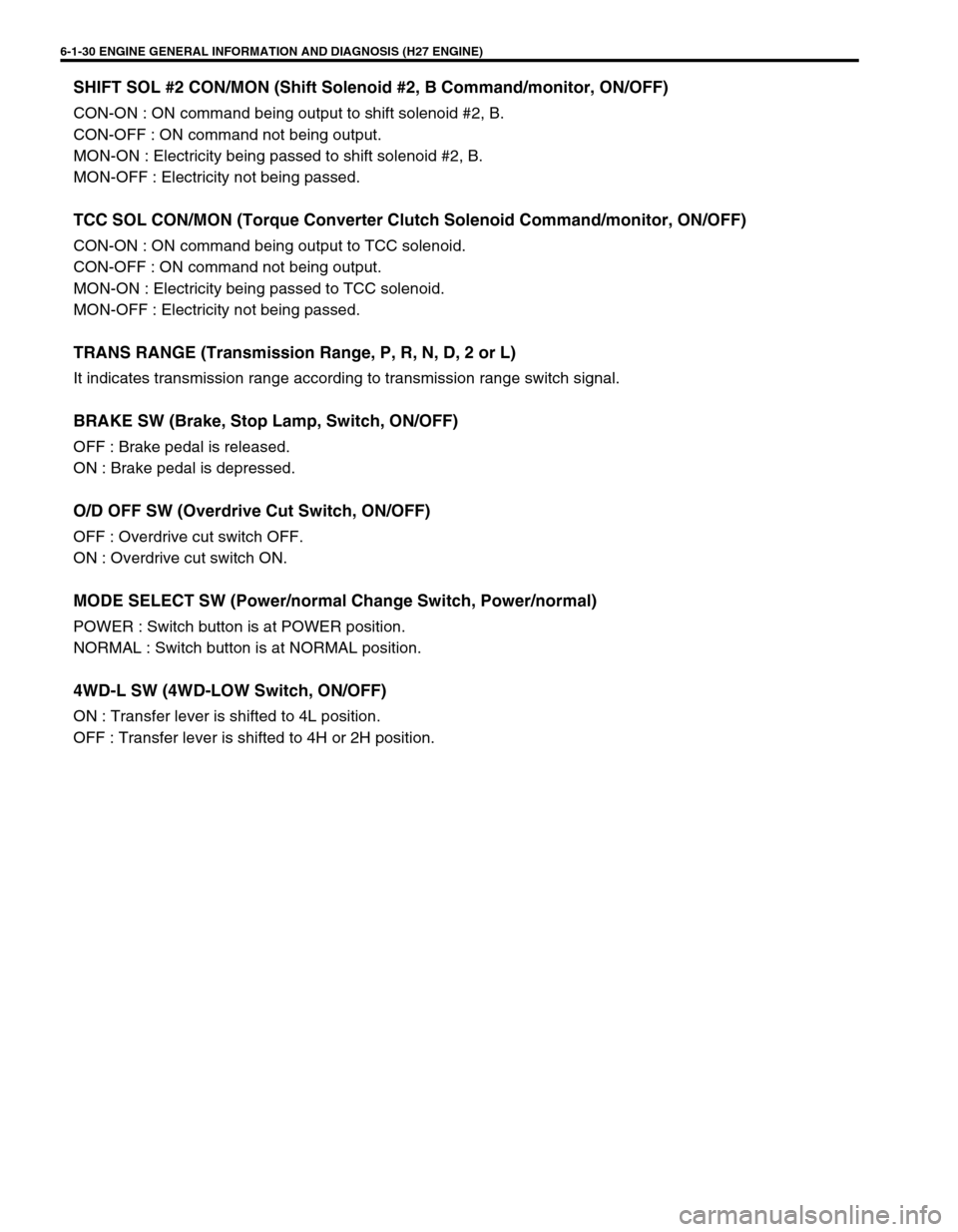
SHIFT SOL #2 CON/MON (Shift Solenoid #2, B Command/monitor, ON/OFF)
CON-ON : ON command being output to shift solenoid #2, B.
CON-OFF : ON command not being output.
MON-ON : Electricity being passed to shift solenoid #2, B.
MON-OFF : Electricity not being passed.
TCC SOL CON/MON (Torque Converter Clutch Solenoid Command/monitor, ON/OFF)
CON-ON : ON command being output to TCC solenoid.
CON-OFF : ON command not being output.
MON-ON : Electricity being passed to TCC solenoid.
MON-OFF : Electricity not being passed.
TRANS RANGE (Transmission Range, P, R, N, D, 2 or L)
It indicates transmission range according to transmission range switch signal.
BRAKE SW (Brake, Stop Lamp, Switch, ON/OFF)
OFF : Brake pedal is released.
ON : Brake pedal is depressed.
O/D OFF SW (Overdrive Cut Switch, ON/OFF)
OFF : Overdrive cut switch OFF.
ON : Overdrive cut switch ON.
MODE SELECT SW (Power/normal Change Switch, Power/normal)
POWER : Switch button is at POWER position.
NORMAL : Switch button is at NORMAL position.
4WD-L SW (4WD-LOW Switch, ON/OFF)
ON : Transfer lever is shifted to 4L position.
OFF : Transfer lever is shifted to 4H or 2H position.
Page 198 of 656
ENGINE GENERAL INFORMATION AND DIAGNOSIS (H27 ENGINE) 6-1-37
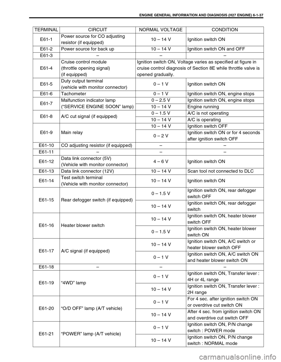
TERMINAL CIRCUIT NORMAL VOLTAGE CONDITION
E61-1Power source for CO adjusting
resistor (if equipped)10 – 14 V Ignition switch ON
E61-2 Power source for back up 10 – 14 V Ignition switch ON and OFF
E61-3 – – –
E61-4Cruise control module
(throttle opening signal)
(if equipped)Ignition switch ON, Voltage varies as specified at figure in
cruise control diagnosis of Section 8E while throttle valve is
opened gradually.
E61-5Duty output terminal
(vehicle with monitor connector)0 – 1 V Ignition switch ON
E61-6 Tachometer 0 – 1 V Ignition switch ON, engine stops
E61-7Malfunction indicator lamp
(“SERVICE ENGINE SOON” lamp)0 – 2.5 V Ignition switch ON, engine stops
10 – 14 V Engine running
E61-8 A/C cut signal (if equipped)0 – 1.5 V A/C is not operating
10 – 14 V A/C is operating
E61-9 Main relay10 – 14 V Ignition switch OFF
0 – 2 VIgnition switch ON or for 4 seconds
after ignition switch OFF
E61-10 CO adjusting resistor (if equipped) – –
E61-11 – – –
E61-12Data link connector (5V)
(Vehicle with monitor connector)4 – 6 V Ignition switch ON
E61-13 Data link connector (12V) 10 – 14 V Scan tool not connected to DLC
E61-14Test switch terminal
(Vehicle with monitor connector)10 – 14 V Ignition switch ON
E61-15 Rear defogger switch (if equipped)0 – 1.5 VIgnition switch ON, rear defogger
switch OFF
10 – 14 VIgnition switch ON, rear defogger
switch
E61-16 Heater blower switch10 – 14 VIgnition switch ON, heater blower
switch OFF
0 – 1.5 VIgnition switch ON, heater blower
switch ON
E61-17 A/C signal (if equipped)10 – 14 VIgnition switch ON, A/C switch or
heater blower switch OFF
0 – 1 VIgnition switch ON, A/C switch ON
and heater blower switch ON
E61-18 – – –
E61-19 “4WD” lamp0 – 1 VIgnition switch ON, Transfer lever :
4H or 4L range
10 – 14 VIgnition switch ON, Transfer lever :
2H range
E61-20 “O/D OFF” lamp (A/T vehicle)0 – 1 VFor 4 sec. after ignition switch ON
or overdrive cut switch ON
10 – 14 VAfter 4 sec. from ignition switch ON
and overdrive cut switch OFF
E61-21 “POWER” lamp (A/T vehicle)0 – 1 VIgnition switch ON, P/N change
switch : POWER mode
10 – 14 VIgnition switch ON, P/N change
switch : NORMAL mode
Page 199 of 656

6-1-38 ENGINE GENERAL INFORMATION AND DIAGNOSIS (H27 ENGINE)
E61-22A/C condenser fan motor relay
(if equipped)10 – 14 VIgnition switch ON, A/C not oper-
ated and Engine coolant temp. :
less than 113°C, 235°F
E61-23 Fuel pump relay0 – 2.5 VFor 3 sec. after ignition switch ON
or while engine running
10 – 14 VAfter 3 sec. from ignition switch ON
with engine stopped
E61-24Ground for CO adjusting resistor
(if equipped)––
E61-25 – – –
E61-26 – – –
E61-27 – – –
E61-28 Fuel level sensor 0 – 6 VIgnition switch ON
Voltage depends on fuel level
E61-29Diag. switch terminal
(vehicle with monitor connector)10 – 14 V Ignition switch ON
E61-30 ABS control module 10 – 14 V Ignition switch ON
E61-31Power/Normal change switch
(A/T vehicle)0 – 1 VIgnition switch ON, P/N change
switch : POWER mode
10 – 14 VIgnition switch ON, P/N change
switch : NORMAL mode
E61-32 Lighting switch0 – 1 VIgnition switch ON, lighting switch
OFF
10 – 14 VIgnition switch ON, lighting switch
ON
E61-33 Overdrive cut switch (A/T vehicle)10 – 14 VIgnition switch ON, overdrive cut
switch released
0 – 1 VIgnition switch ON, overdrive cut
switch pressed
E61-34 Stop lamp switch0 – 1 VBrake pedal released (switch OFF),
Ignition switch ON
10 – 14 VBrake pedal depressed (switch ON),
Ignition switch ON
E61-35 Cruise control module (if equipped) 10 – 14 V Ignition switch ON
C51-3-1 Intake air temp. sensor 2.2 – 3.0 VIgnition switch ON, Sensor ambient
temp. : 20°C, 68°F
C51-3-2 Engine coolant temp. sensor 0.5 – 0.9 VIgnition switch ON, Engine coolant
temp. : 80°C, 176°F
C51-3-3 Knock sensor About 2.5 VWith engine running at idle after
warned up
C51-3-4 Power source 10 – 14 V Ignition switch ON
C51-3-5 Ground for MAF sensor – –
C51-3-6 Ground – –
C51-3-7 4WD switch0 – 1 VIgnition switch ON, Transfer lever :
4H or 4L range
10 – 14 VIgnition switch ON, Transfer lever :
2H range
C51-3-8 Manifold absolute pressure sensor 3.3 – 4.3 V Ignition switch ON and engine stops TERMINAL CIRCUIT NORMAL VOLTAGE CONDITION
Page 200 of 656

ENGINE GENERAL INFORMATION AND DIAGNOSIS (H27 ENGINE) 6-1-39
C51-3-9 Throttle position sensor0.5 – 1.2 VIgnition switch ON, Throttle valve at
idle position
3.4 – 4.7 VIgnition switch ON, Throttle valve at
full open position
C51-3-10 Mass air flow sensor1.0 – 1.6 V Ignition switch ON and engine stops
1.7 – 2.0 V With engine running at idle speed
C51-3-11Heated oxygen sensor-1 (bank 1)
(if equipped)Deflects between
over and under 0.45 VWhile engine running at 2,000 r/min.
for 1 min. or longer after warmed up
C51-3-12 Ground for TP sensor – –
C51-3-13 Power source for TP sensor
4.75 – 5.25 V Ignition switch ON
C51-3-14 Power source for MAP sensor
C51-3-15 Power source 10 – 14 V Ignition switch ON
C51-3-16 – – –
C51-3-17 Ground – –
C51-3-18Pressure switch in 4WD air pump
assembly10 – 14 VIgnition switch ON, Transfer lever :
4H or 4L range
0 – 1 VIgnition switch ON, Transfer lever :
2H range
C51-3-19 – – –
C51-3-20 Ignition switch 10 – 14 V Ignition switch ON
C51-3-21Heated oxygen sensor-1 (bank 2)
(if equipped)Deflects between over
and under 0.45 VWhile engine running at 2,000 r/min.
for 1 min. or longer after warmed up
C51-3-22Heated oxygen sensor-2 (bank 1)
(if equipped)Deflects between over
and under 0.45 VWhile engine running at 2,000 r/min.
for 1 min. or longer after warmed up
C51-3-23Heated oxygen sensor-2 (bank 2)
(if equipped)Deflects between over
and under 0.45 VWhile engine running at 2,000 r/min.
for 1 min. or longer after warmed up
C51-3-24 Ground for ECT sensor – –
C51-3-25 Ground for IAT sensor, MAP sensor – –
C51-3-26 Ground for CMP sensor – –
C51-1-1 Shift solenoid B (A/T vehicle) 0 – 1 V Ignition switch ON
C51-1-2 Shift solenoid A (A/T vehicle) 10 – 14 V Ignition switch ON
C51-1-3 – – –
C51-1-4 IAC valve (stepper motor coil 2) – –
C51-1-5 IAC valve (stepper motor coil 1) – –
C51-1-6Transmission range switch “R”
(A/T vehicle)10 – 14 VIgnition switch ON, selector lever :
“R” range
0 – 1 VIgnition switch ON, selector lever :
Other than “R”
C51-1-7Transmission range switch “P”
(A/T vehicle)10 – 14 VIgnition switch ON, selector lever :
“P” range
0 – 1 VIgnition switch ON, selector lever :
Other than “P” range
C51-1-8 TCC solenoid (A/T vehicle) 0 – 1 V Ignition switch ON
C51-1-9 4WD air pump assembly10 – 14 VIgnition switch ON, Transfer lever :
4H or 4L range
0 – 1 VIgnition switch ON, Transfer lever :
2H range TERMINAL CIRCUIT NORMAL VOLTAGE CONDITION
Page 201 of 656

6-1-40 ENGINE GENERAL INFORMATION AND DIAGNOSIS (H27 ENGINE)
C51-1-10A/T input speed sensor (–)
(A/T vehicle)About 2.5 V Ignition switch ON
C51-1-11A/T input speed sensor (+)
(A/T vehicle)About 2.5 V Ignition switch ON
C51-1-12 Camshaft position sensor 1Deflects between
0 – 1 V and 4 – 6 VIgnition switch ON, crankshaft
turned slowly
C51-1-13 Camshaft position sensor 2Deflects between
0 – 1 V and 4 – 6 VIgnition switch ON, crankshaft
turned slowly
C51-1-14 Vehicle speed sensorDeflects between
0 – 1 V and over 4VIgnition switch ON, Rear right tire
turned slowly with rear left tire
locked
C51-1-15 EVAP canister purge valve 10 – 14 V Ignition switch ON
C51-1-16 IAC valve (stepper motor coil 4) – –
C51-1-17 IAC valve (stepper motor coil 3) – –
C51-1-18Transmission range switch “D”
(A/T vehicle)10 – 14 VIgnition switch ON, selector lever :
“D” range
0 – 1 VIgnition switch ON, selector lever :
Other than “D” range
C51-1-19Transmission range switch “N”
(A/T vehicle)10 – 14 VIgnition switch ON, selector lever :
“N” range
0 – 1 VIgnition switch ON, selector lever :
Other than “N” range
C51-1-20Shield wire ground for A/T output
speed sensor (A/T vehicle)––
C51-1-21Shield wire ground for A/T input
speed sensor (A/T vehicle)––
C51-1-22A/T output speed sensor (–)
(A/T vehicle)About 2.5 V Ignition switch ON
C51-1-23A/T output speed sensor (+)
(A/T vehicle)About 2.5 V Ignition switch ON
C51-1-24 Engine start signal10 – 14 V While engine cranking
0 – 1 V Other than above
C51-1-25 Power steering pressure switch10 – 14 V Ignition switch ON
0 – 1 VWith engine running at idle speed,
turning steering wheel to the right or
left as far as it stops
C51-1-26 4WD low switch0 – 1 VIgnition switch ON, Transfer lever :
4WD low range
10 – 14 VIgnition switch ON, Transfer lever :
4H or 2H range
C51-1-27Transmission range switch “L”
(A/T vehicle)10 – 14 VIgnition switch ON, selector lever :
“L” range
0 – 1 VIgnition switch ON, selector lever :
Other than “L” range
C51-1-28Transmission range switch “2”
(A/T vehicle)10 – 14 VIgnition switch ON, selector lever :
“2” range
0 – 1 VIgnition switch ON, selector lever :
Other than “2” range TERMINAL CIRCUIT NORMAL VOLTAGE CONDITION
Page 221 of 656
6-1-60 ENGINE GENERAL INFORMATION AND DIAGNOSIS (H27 ENGINE)
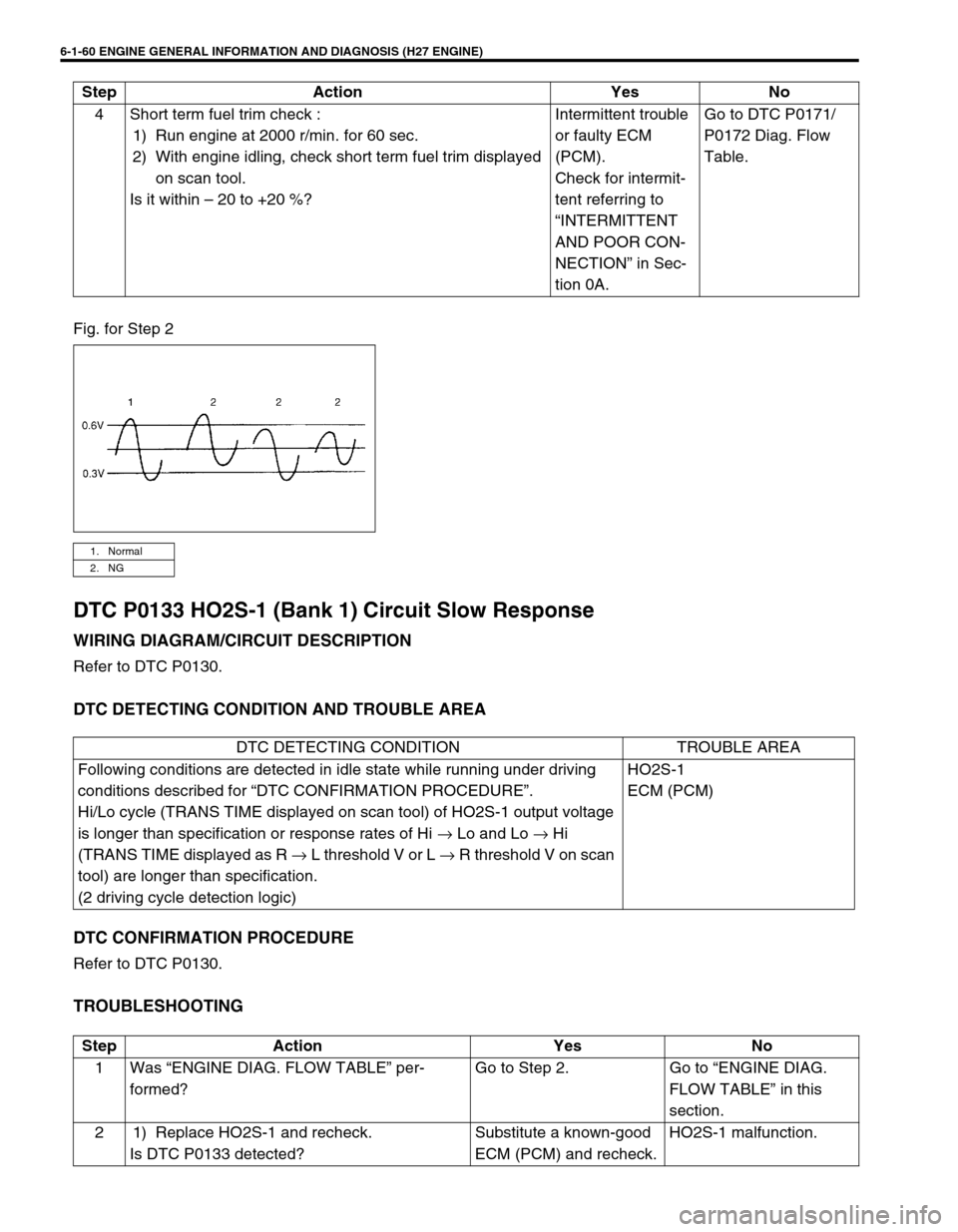
Fig. for Step 2
DTC P0133 HO2S-1 (Bank 1) Circuit Slow Response
WIRING DIAGRAM/CIRCUIT DESCRIPTION
Refer to DTC P0130.
DTC DETECTING CONDITION AND TROUBLE AREA
DTC CONFIRMATION PROCEDURE
Refer to DTC P0130.
TROUBLESHOOTING
4 Short term fuel trim check :
1) Run engine at 2000 r/min. for 60 sec.
2) With engine idling, check short term fuel trim displayed
on scan tool.
Is it within – 20 to +20 %?Intermittent trouble
or faulty ECM
(PCM).
Check for intermit-
tent referring to
“INTERMITTENT
AND POOR CON-
NECTION” in Sec-
tion 0A.Go to DTC P0171/
P0172 Diag. Flow
Table. Step Action Yes No
1. Normal
2. NG
DTC DETECTING CONDITION TROUBLE AREA
Following conditions are detected in idle state while running under driving
conditions described for “DTC CONFIRMATION PROCEDURE”.
Hi/Lo cycle (TRANS TIME displayed on scan tool) of HO2S-1 output voltage
is longer than specification or response rates of Hi → Lo and Lo → Hi
(TRANS TIME displayed as R → L threshold V or L → R threshold V on scan
tool) are longer than specification.
(2 driving cycle detection logic)HO2S-1
ECM (PCM)
Step Action Yes No
1 Was “ENGINE DIAG. FLOW TABLE” per-
formed?Go to Step 2. Go to “ENGINE DIAG.
FLOW TABLE” in this
section.
2 1) Replace HO2S-1 and recheck.
Is DTC P0133 detected?Substitute a known-good
ECM (PCM) and recheck.HO2S-1 malfunction.
Page 230 of 656
ENGINE GENERAL INFORMATION AND DIAGNOSIS (H27 ENGINE) 6-1-69
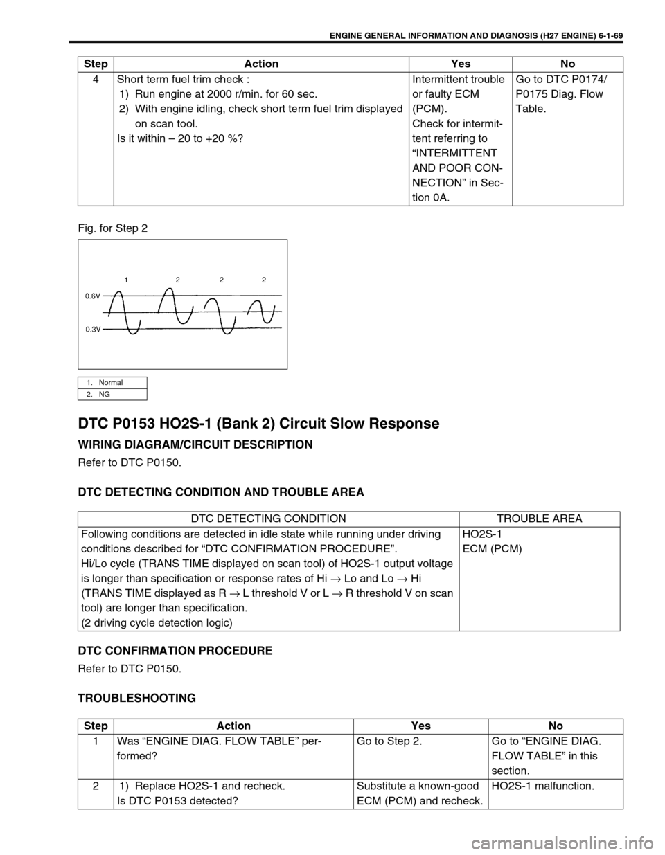
Fig. for Step 2
DTC P0153 HO2S-1 (Bank 2) Circuit Slow Response
WIRING DIAGRAM/CIRCUIT DESCRIPTION
Refer to DTC P0150.
DTC DETECTING CONDITION AND TROUBLE AREA
DTC CONFIRMATION PROCEDURE
Refer to DTC P0150.
TROUBLESHOOTING
4 Short term fuel trim check :
1) Run engine at 2000 r/min. for 60 sec.
2) With engine idling, check short term fuel trim displayed
on scan tool.
Is it within – 20 to +20 %?Intermittent trouble
or faulty ECM
(PCM).
Check for intermit-
tent referring to
“INTERMITTENT
AND POOR CON-
NECTION” in Sec-
tion 0A.Go to DTC P0174/
P0175 Diag. Flow
Table. Step Action Yes No
1. Normal
2. NG
DTC DETECTING CONDITION TROUBLE AREA
Following conditions are detected in idle state while running under driving
conditions described for “DTC CONFIRMATION PROCEDURE”.
Hi/Lo cycle (TRANS TIME displayed on scan tool) of HO2S-1 output voltage
is longer than specification or response rates of Hi → Lo and Lo → Hi
(TRANS TIME displayed as R → L threshold V or L → R threshold V on scan
tool) are longer than specification.
(2 driving cycle detection logic)HO2S-1
ECM (PCM)
Step Action Yes No
1 Was “ENGINE DIAG. FLOW TABLE” per-
formed?Go to Step 2. Go to “ENGINE DIAG.
FLOW TABLE” in this
section.
2 1) Replace HO2S-1 and recheck.
Is DTC P0153 detected?Substitute a known-good
ECM (PCM) and recheck.HO2S-1 malfunction.
Page 261 of 656
6-1-100 ENGINE GENERAL INFORMATION AND DIAGNOSIS (H27 ENGINE)
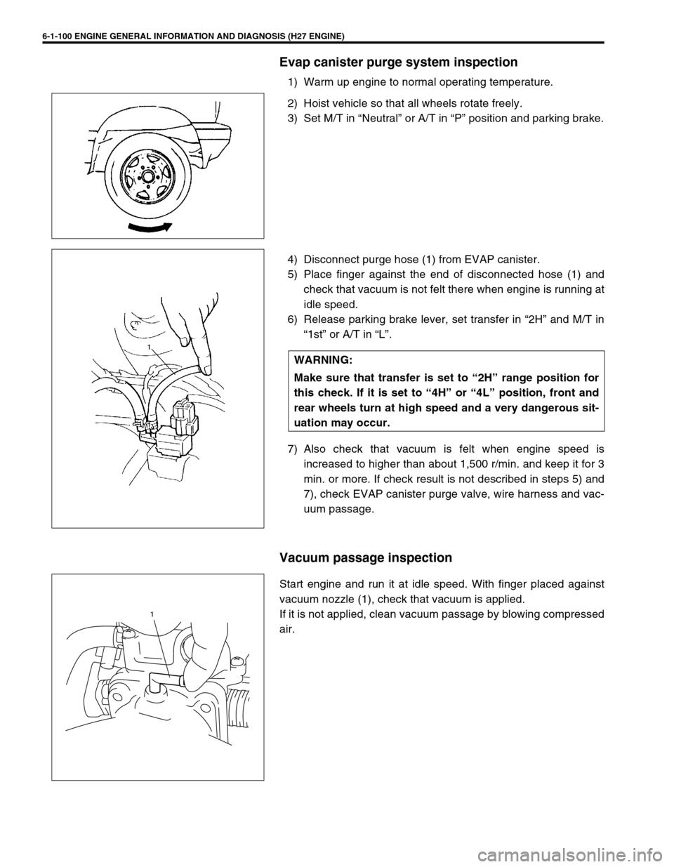
Evap canister purge system inspection
1) Warm up engine to normal operating temperature.
2) Hoist vehicle so that all wheels rotate freely.
3) Set M/T in “Neutral” or A/T in “P” position and parking brake.
4) Disconnect purge hose (1) from EVAP canister.
5) Place finger against the end of disconnected hose (1) and
check that vacuum is not felt there when engine is running at
idle speed.
6) Release parking brake lever, set transfer in “2H” and M/T in
“1st” or A/T in “L”.
7) Also check that vacuum is felt when engine speed is
increased to higher than about 1,500 r/min. and keep it for 3
min. or more. If check result is not described in steps 5) and
7), check EVAP canister purge valve, wire harness and vac-
uum passage.
Vacuum passage inspection
Start engine and run it at idle speed. With finger placed against
vacuum nozzle (1), check that vacuum is applied.
If it is not applied, clean vacuum passage by blowing compressed
air.
WARNING:
Make sure that transfer is set to “2H” range position for
this check. If it is set to “4H” or “4L” position, front and
rear wheels turn at high speed and a very dangerous sit-
uation may occur.
1