Page 311 of 656
6A2-24 ENGINE MECHANICAL (H27 ENGINE)
ASSEMBLY
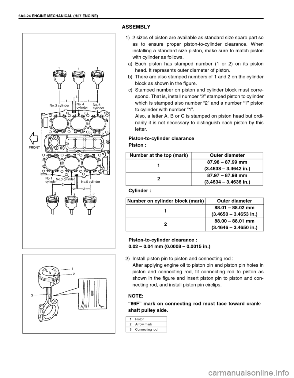
1) 2 sizes of piston are available as standard size spare part so
as to ensure proper piston-to-cylinder clearance. When
installing a standard size piston, make sure to match piston
with cylinder as follows.
a) Each piston has stamped number (1 or 2) on its piston
head. It represents outer diameter of piston.
b) There are also stamped numbers of 1 and 2 on the cylinder
block as shown in the figure.
c) Stamped number on piston and cylinder block must corre-
spond. That is, install number “2” stamped piston to cylinder
which is stamped also number “2” and a number “1” piston
to cylinder with number “1”.
Also, a letter A, B or C is stamped on piston head but ordi-
narily it is not necessary to distinguish each piston by this
letter.
Piston-to-cylinder clearance
Piston :
Cylinder :
Piston-to-cylinder clearance :
0.02 – 0.04 mm (0.0008 – 0.0015 in.)
2) Install piston pin to piston and connecting rod :
After applying engine oil to piston pin and piston pin holes in
piston and connecting rod, fit connecting rod to piston as
shown in the figure and insert piston pin to piston and con-
necting rod, and install piston pin circlips. Number at the top (mark) Outer diameter
187.98 – 87.99 mm
(3.4638 – 3.4642 in.)
287.97 – 87.98 mm
(3.4634 – 3.4638 in.)
Number on cylinder block (mark) Outer diameter
188.01 – 88.02 mm
(3.4650 – 3.4653 in.)
288.00 – 88.01 mm
(3.4646 – 3.4650 in.)
NOTE:
“86F” mark on connecting rod must face toward crank-
shaft pulley side.
1. Piston
2. Arrow mark
3. Connecting rod
Page 312 of 656
ENGINE MECHANICAL (H27 ENGINE) 6A2-25
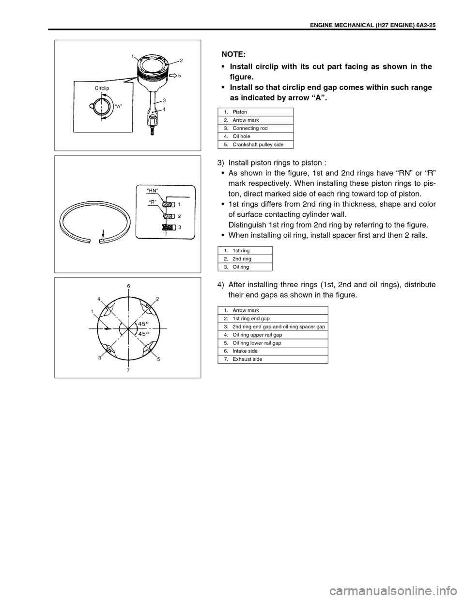
3) Install piston rings to piston :
•As shown in the figure, 1st and 2nd rings have “RN” or “R”
mark respectively. When installing these piston rings to pis-
ton, direct marked side of each ring toward top of piston.
•1st rings differs from 2nd ring in thickness, shape and color
of surface contacting cylinder wall.
Distinguish 1st ring from 2nd ring by referring to the figure.
•When installing oil ring, install spacer first and then 2 rails.
4) After installing three rings (1st, 2nd and oil rings), distribute
their end gaps as shown in the figure. NOTE:
Install circlip with its cut part facing as shown in the
figure.
Install so that circlip end gap comes within such range
as indicated by arrow “A”.
1. Piston
2. Arrow mark
3. Connecting rod
4. Oil hole
5. Crankshaft pulley side
1. 1st ring
2. 2nd ring
3. Oil ring
1. Arrow mark
2. 1st ring end gap
3. 2nd ring end gap and oil ring spacer gap
4. Oil ring upper rail gap
5. Oil ring lower rail gap
6. Intake side
7. Exhaust side
Page 313 of 656
6A2-26 ENGINE MECHANICAL (H27 ENGINE)
Unit Repair Overhaul
Engine Assembly
REMOVAL
1) Release fuel pressure in fuel feed line. Refer to “FUEL
PRESSURE RELIEF PROCEDURE” in Section 6.
2) Disconnect negative (–) cable at battery.
3) Remove engine hood.
4) Drain engine oil.
5) Drain coolant.
6) Remove radiator, radiator fan shroud, cooling fan and radia-
tor reservoir. Refer to “COOLING FAN AND FAN CLUTCH”
and “RADIATOR” in Section 6B.
7) Disconnect accelerator cable (1) and A/T throttle cable (for
A/T vehicle) (2) from throttle body.
8) Remove strut tower bar and surge tank cover.
9) Disconnect IAT sensor coupler and MAF sensor coupler then
remove air cleaner upper case, intake air hose, intake air
pipe and surge tank pipe as a component.
10) Remove engine oil level gauge guide and A/T fluid level
gauge guide (for A/T vehicle).
11) Remove ignition coil covers.
12
Page 315 of 656
6A2-28 ENGINE MECHANICAL (H27 ENGINE)
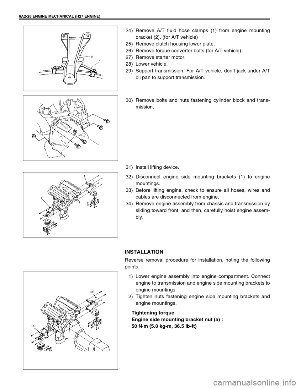
24) Remove A/T fluid hose clamps (1) from engine mounting
bracket (2). (for A/T vehicle)
25) Remove clutch housing lower plate.
26) Remove torque converter bolts (for A/T vehicle).
27) Remove starter motor.
28) Lower vehicle.
29) Support transmission. For A/T vehicle, don’t jack under A/T
oil pan to support transmission.
30) Remove bolts and nuts fastening cylinder block and trans-
mission.
31) Install lifting device.
32) Disconnect engine side mounting brackets (1) to engine
mountings.
33) Before lifting engine, check to ensure all hoses, wires and
cables are disconnected from engine.
34) Remove engine assembly from chassis and transmission by
sliding toward front, and then, carefully hoist engine assem-
bly.
INSTALLATION
Reverse removal procedure for installation, noting the following
points.
1) Lower engine assembly into engine compartment. Connect
engine to transmission and engine side mounting brackets to
engine mountings.
2) Tighten nuts fastening engine side mounting brackets and
engine mountings.
Tightening torque
Engine side mounting bracket nut (a) :
50 N·m (5.0 kg-m, 36.5 lb-ft)
Page 351 of 656
6E2-18 ENGINE AND EMISSION CONTROL SYSTEM (SEQUENTIAL MULTIPORT FUEL INJECTION FOR H27 ENGINE)
Air Intake System
Throttle body
REMOVAL
1) Disconnect negative (–) cable at battery.
2) Drain cooling system.
3) Remove strut tower bar.
4) Disconnect accelerator cable (1) and or A/T throttle cable (2)
from throttle body.
5) Disconnect water hoses from throttle body.
1. Throttle body 4. Water hose
2. Intake collector 5. MAF sensor
3. Breather hose 6. TP sensor
Page 354 of 656
ENGINE AND EMISSION CONTROL SYSTEM (SEQUENTIAL MULTIPORT FUEL INJECTION FOR H27 ENGINE) 6E2-21
14) Install strut tower bar (1) and tighten bolts.
15) Refill cooling system.
16) Connect negative (–) cable at battery.
17) Adjust accelerator cable and A/T throttle cable, refer to
“ACCELERATOR CABLE ADJUSTMENT” and “A/T THROT-
TLE CABLE ADJUSTMENT” in this section.
Idle air control valve (IAC valve)
REMOVAL
1) Disconnect negative (–) cable at battery.
2) Disconnect IAC valve connector.
3) Remove IAC valve (1) from throttle body.
INSPECTION
1) Disconnect connector from IAC valve.
2) Check each coil of IAC valve for resistance.
If resistances is out of specification, replace.
IAC valve resistance:
Terminals Resistance
Between “1” and “2”
25.5 - 33.5 Ω
ΩΩ Ω Between “3” and “2”
Between “4” and “5”
Between “6” and “5”
Page 573 of 656
10A-4 SEAT BELT
REMOVAL
1) Disconnect negative cable at battery.
2) Disable air bag system referring to “DISABLING AIR BAG SYSTEM” of “SERVICE PRECAUTIONS” under
“ON-VEHICLE SERVICE” in Section 10B, if necessary.
3) Remove front pillar lower trim.
4) Disconnect Yellow connector for seat belt pretensioner, if necessary.
a) Release locking of lock lever.
b) After unlocking, disconnect to connector.
5) Remove front seat belts from the vehicle.
INSPECTION
Seat belts and attaching parts can affect the vital components and systems of a vehicle. Therefore, they should
be inspected carefully and replaced with genuine parts only.
Seat belt
•The seat belt webbing or strap should be free from damage.
•Fully extend the seat belt to make sure there are no twists or tears in it.
Retractor assembly
1) Let the seat belt retract fully to confirm its easy retraction.
•The retractor assembly should lock webbing when pulled quickly.
•The retractor assembly should lock webbing even when tilted (approx. 15°) toward the fore and aft or right
and left directions.
2) Check retractor assembly with seat belt pretensioner appearance visually for following symptoms and if any
one of them is applicable, replace it with a new one as an assembly.
•Pretensioner has activated.
•There is a crack in seat belt pretensioner (retractor assembly).
•Wire harness or connector is damage.
•Seat belt pretensioner (retractor assembly) is damaged or a strong impact (e.g., dropping) was applied to it.
Anchor bolt
•Inspect all seat belt anchor bolts to verify that they are secure.
•All anchor bolts should be secure and torqued to specification.
Belt latch
•Belt latch should be secure when latched.
•Inspect the seat belt buckle, ensuring that it locks and unlocks easily.
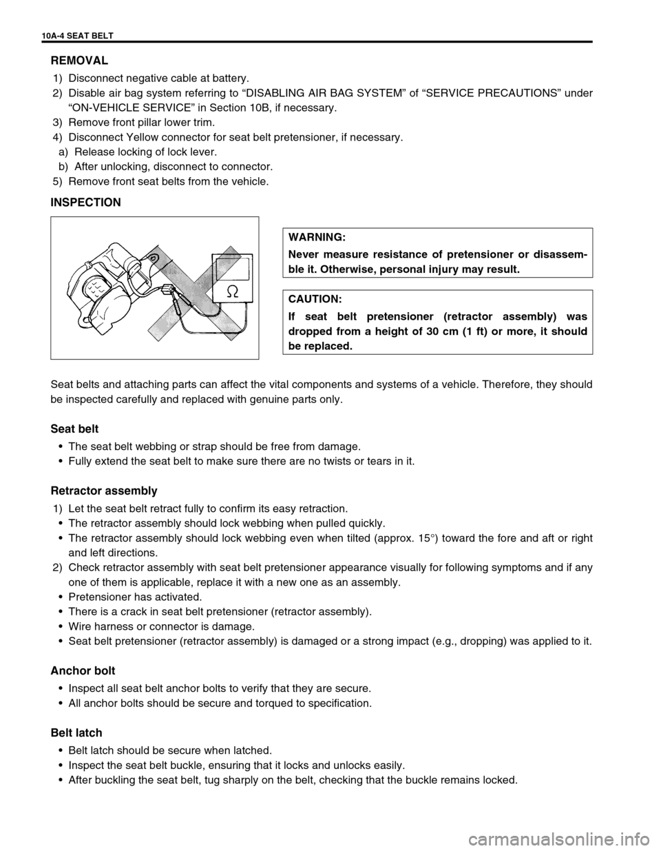
•After buckling the seat belt, tug sharply on the belt, checking that the buckle remains locked.WARNING:
Never measure resistance of pretensioner or disassem-
ble it. Otherwise, personal injury may result.
CAUTION:
If seat belt pretensioner (retractor assembly) was
dropped from a height of 30 cm (1 ft) or more, it should
be replaced.
Page 628 of 656
AIR BAG SYSTEM 10B-51
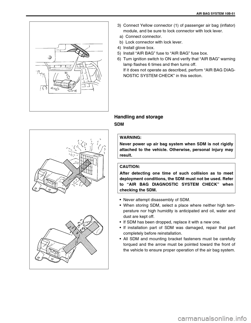
3) Connect Yellow connector (1) of passenger air bag (inflator)
module, and be sure to lock connector with lock lever.
a) Connect connector.
b) Lock connector with lock lever.
4) Install glove box.
5) Install “AIR BAG” fuse to “AIR BAG” fuse box.
6) Turn ignition switch to ON and verify that “AIR BAG” warning
lamp flashes 6 times and then turns off.
If it does not operate as described, perform “AIR BAG DIAG-
NOSTIC SYSTEM CHECK” in this section.
Handling and storage
SDM
•Never attempt disassembly of SDM.
•When storing SDM, select a place where neither high tem-
perature nor high humidity is anticipated and oil, water and
dust are kept off.
•If SDM has been dropped, replace it with a new one.
•If installation part of SDM was damaged, repair that part
completely before reinstallation.
•All SDM and mounting bracket fasteners must be carefully
torqued and the arrow must be pointed toward the front of
the vehicle to ensure proper operation of the air bag system.
WARNING:
Never power up air bag system when SDM is not rigidly
attached to the vehicle. Otherwise, personal injury may
result.
CAUTION:
After detecting one time of such collision as to meet
deployment conditions, the SDM must not be used. Refer
to “AIR BAG DIAGNOSTIC SYSTEM CHECK” when
checking the SDM.