1999 SUBARU FORESTER turn signal
[x] Cancel search: turn signalPage 116 of 345
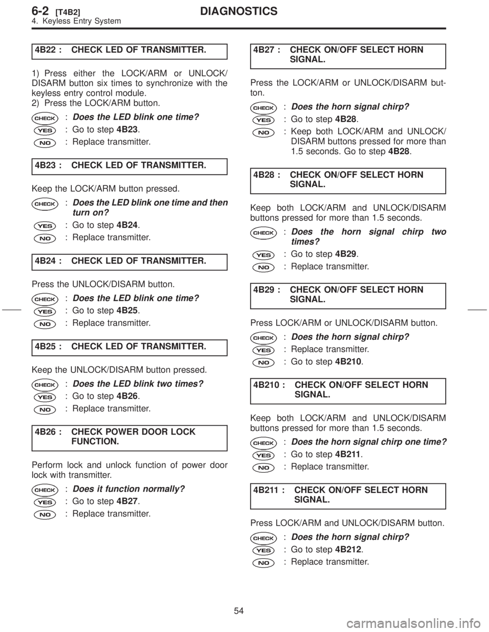
4B22 : CHECK LED OF TRANSMITTER.
1) Press either the LOCK/ARM or UNLOCK/
DISARM button six times to synchronize with the
keyless entry control module.
2) Press the LOCK/ARM button.
:Does the LED blink one time?
: Go to step4B23.
: Replace transmitter.
4B23 : CHECK LED OF TRANSMITTER.
Keep the LOCK/ARM button pressed.
:Does the LED blink one time and then
turn on?
: Go to step4B24.
: Replace transmitter.
4B24 : CHECK LED OF TRANSMITTER.
Press the UNLOCK/DISARM button.
:Does the LED blink one time?
: Go to step4B25.
: Replace transmitter.
4B25 : CHECK LED OF TRANSMITTER.
Keep the UNLOCK/DISARM button pressed.
:Does the LED blink two times?
: Go to step4B26.
: Replace transmitter.
4B26 : CHECK POWER DOOR LOCK
FUNCTION.
Perform lock and unlock function of power door
lock with transmitter.
:Does it function normally?
: Go to step4B27.
: Replace transmitter.4B27 : CHECK ON/OFF SELECT HORN
SIGNAL.
Press the LOCK/ARM or UNLOCK/DISARM but-
ton.
:Does the horn signal chirp?
: Go to step4B28.
: Keep both LOCK/ARM and UNLOCK/
DISARM buttons pressed for more than
1.5 seconds. Go to step4B28.
4B28 : CHECK ON/OFF SELECT HORN
SIGNAL.
Keep both LOCK/ARM and UNLOCK/DISARM
buttons pressed for more than 1.5 seconds.
:Does the horn signal chirp two
times?
: Go to step4B29.
: Replace transmitter.
4B29 : CHECK ON/OFF SELECT HORN
SIGNAL.
Press LOCK/ARM or UNLOCK/DISARM button.
:Does the horn signal chirp?
: Replace transmitter.
: Go to step4B210.
4B210 : CHECK ON/OFF SELECT HORN
SIGNAL.
Keep both LOCK/ARM and UNLOCK/DISARM
buttons pressed for more than 1.5 seconds.
:Does the horn signal chirp one time?
: Go to step4B211.
: Replace transmitter.
4B211 : CHECK ON/OFF SELECT HORN
SIGNAL.
Press LOCK/ARM and UNLOCK/DISARM button.
:Does the horn signal chirp?
: Go to step4B212.
: Replace transmitter.
54
6-2[T4B2]DIAGNOSTICS
4. Keyless Entry System
Page 122 of 345
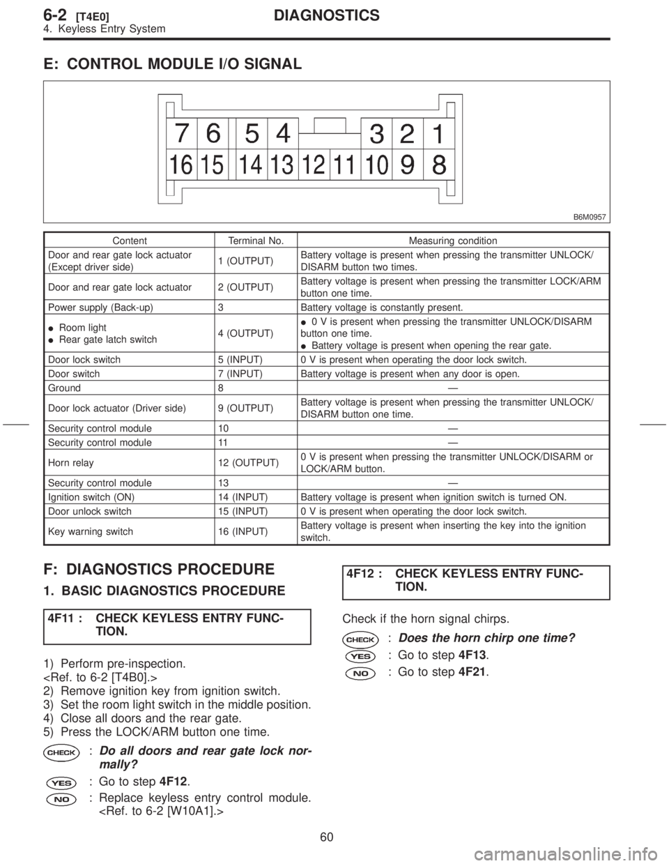
E: CONTROL MODULE I/O SIGNAL
B6M0957
Content Terminal No. Measuring condition
Door and rear gate lock actuator
(Except driver side)1 (OUTPUT)Battery voltage is present when pressing the transmitter UNLOCK/
DISARM button two times.
Door and rear gate lock actuator 2 (OUTPUT)Battery voltage is present when pressing the transmitter LOCK/ARM
button one time.
Power supply (Back-up) 3 Battery voltage is constantly present.
IRoom light
IRear gate latch switch4 (OUTPUT)I0 V is present when pressing the transmitter UNLOCK/DISARM
button one time.
IBattery voltage is present when opening the rear gate.
Door lock switch 5 (INPUT) 0 V is present when operating the door lock switch.
Door switch 7 (INPUT) Battery voltage is present when any door is open.
Ground 8 Ð
Door lock actuator (Driver side) 9 (OUTPUT)Battery voltage is present when pressing the transmitter UNLOCK/
DISARM button one time.
Security control module 10 Ð
Security control module 11 Ð
Horn relay 12 (OUTPUT)0 V is present when pressing the transmitter UNLOCK/DISARM or
LOCK/ARM button.
Security control module 13 Ð
Ignition switch (ON) 14 (INPUT) Battery voltage is present when ignition switch is turned ON.
Door unlock switch 15 (INPUT) 0 V is present when operating the door lock switch.
Key warning switch 16 (INPUT)Battery voltage is present when inserting the key into the ignition
switch.
F: DIAGNOSTICS PROCEDURE
1. BASIC DIAGNOSTICS PROCEDURE
4F11 : CHECK KEYLESS ENTRY FUNC-
TION.
1) Perform pre-inspection.
2) Remove ignition key from ignition switch.
3) Set the room light switch in the middle position.
4) Close all doors and the rear gate.
5) Press the LOCK/ARM button one time.
:Do all doors and rear gate lock nor-
mally?
: Go to step4F12.
: Replace keyless entry control module.
TION.
Check if the horn signal chirps.
:Does the horn chirp one time?
: Go to step4F13.
: Go to step4F21.
60
6-2[T4E0]DIAGNOSTICS
4. Keyless Entry System
Page 123 of 345
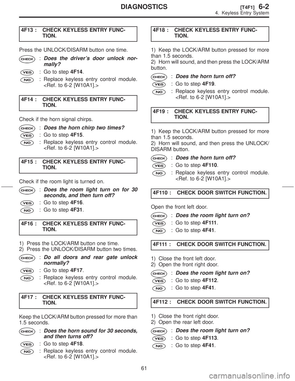
4F13 : CHECK KEYLESS ENTRY FUNC-
TION.
Press the UNLOCK/DISARM button one time.
:Does the driver's door unlock nor-
mally?
: Go to step4F14.
: Replace keyless entry control module.
4F14 : CHECK KEYLESS ENTRY FUNC-
TION.
Check if the horn signal chirps.
:Does the horn chirp two times?
: Go to step4F15.
: Replace keyless entry control module.
4F15 : CHECK KEYLESS ENTRY FUNC-
TION.
Check if the room light is turned on.
:Does the room light turn on for 30
seconds, and then turn off?
: Go to step4F16.
: Go to step4F31.
4F16 : CHECK KEYLESS ENTRY FUNC-
TION.
1) Press the LOCK/ARM button one time.
2) Press the UNLOCK/DISARM button two times.
:Do all doors and rear gate unlock
normally?
: Go to step4F17.
: Replace keyless entry control module.
4F17 : CHECK KEYLESS ENTRY FUNC-
TION.
Keep the LOCK/ARM button pressed for more than
1.5 seconds.
:Does the horn sound for 30 seconds,
and then turns off?
: Go to step4F18.
: Replace keyless entry control module.
TION.
1) Keep the LOCK/ARM button pressed for more
than 1.5 seconds.
2) Horn will sound, and then press the LOCK/ARM
button.
:Does the horn turn off?
: Go to step4F19.
: Replace keyless entry control module.
4F19 : CHECK KEYLESS ENTRY FUNC-
TION.
1) Keep the LOCK/ARM button pressed for more
than 1.5 seconds.
2) Horn will sound, and then press the UNLOCK/
DISARM button.
:Does the horn turn off?
: Go to step4F110.
: Replace keyless entry control module.
4F110 : CHECK DOOR SWITCH FUNCTION.
Open the front left door.
:Does the room light turn on?
: Go to step4 F 111.
: Go to step4F41.
4F111 : CHECK DOOR SWITCH FUNCTION.
1) Close the front left door.
2) Open the front right door.
:Does the room light turn on?
: Go to step4F112.
: Go to step4F41.
4F112 : CHECK DOOR SWITCH FUNCTION.
1) Close the front right door.
2) Open the rear left door.
:Does the room light turn on?
: Go to step4F113.
: Go to step4F41.
61
[T4F1]6-2DIAGNOSTICS
4. Keyless Entry System
Page 136 of 345
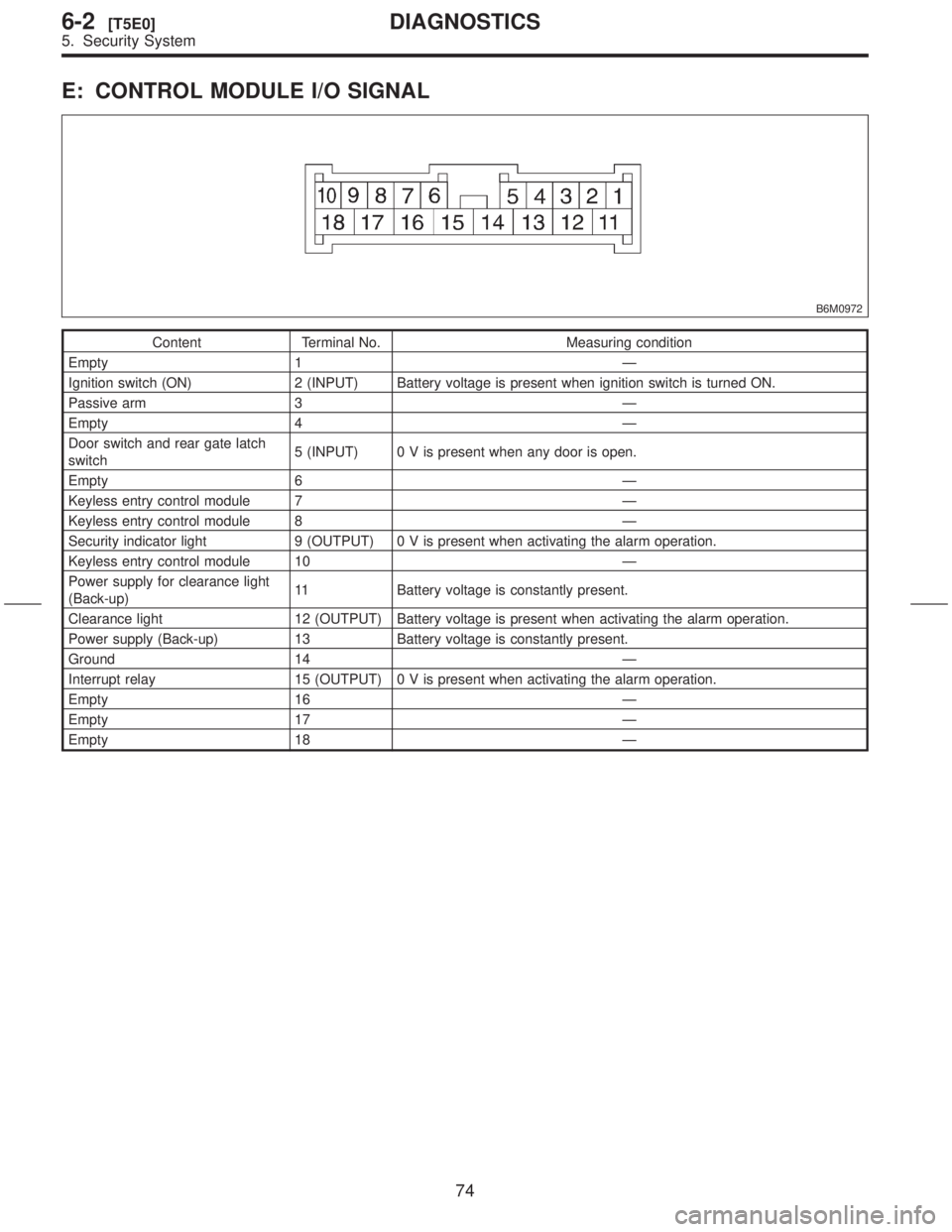
E: CONTROL MODULE I/O SIGNAL
B6M0972
Content Terminal No. Measuring condition
Empty 1 Ð
Ignition switch (ON) 2 (INPUT) Battery voltage is present when ignition switch is turned ON.
Passive arm 3 Ð
Empty 4 Ð
Door switch and rear gate latch
switch5 (INPUT) 0 V is present when any door is open.
Empty 6 Ð
Keyless entry control module 7 Ð
Keyless entry control module 8 Ð
Security indicator light 9 (OUTPUT) 0 V is present when activating the alarm operation.
Keyless entry control module 10 Ð
Power supply for clearance light
(Back-up)11 Battery voltage is constantly present.
Clearance light 12 (OUTPUT) Battery voltage is present when activating the alarm operation.
Power supply (Back-up) 13 Battery voltage is constantly present.
Ground 14 Ð
Interrupt relay 15 (OUTPUT) 0 V is present when activating the alarm operation.
Empty 16 Ð
Empty 17 Ð
Empty 18 Ð
74
6-2[T5E0]DIAGNOSTICS
5. Security System
Page 146 of 345
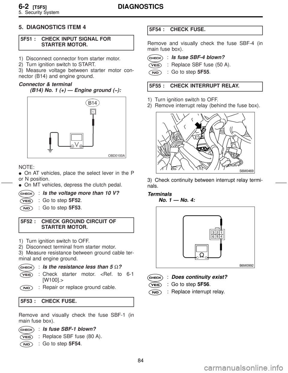
5. DIAGNOSTICS ITEM 4
5F51 : CHECK INPUT SIGNAL FOR
STARTER MOTOR.
1) Disconnect connector from starter motor.
2) Turn ignition switch to START.
3) Measure voltage between starter motor con-
nector (B14) and engine ground.
Connector & terminal
(B14) No. 1 (+) Ð Engine ground (þ):
OBD0100A
NOTE:
IOn AT vehicles, place the select lever in the P
or N position.
IOn MT vehicles, depress the clutch pedal.
:Is the voltage more than 10 V?
: Go to step5F52.
: Go to step5F53.
5F52 : CHECK GROUND CIRCUIT OF
STARTER MOTOR.
1) Turn ignition switch to OFF.
2) Disconnect terminal from starter motor.
3) Measure resistance between ground cable ter-
minal and engine ground.
:Is the resistance less than 5W?
: Check starter motor.
: Repair or replace ground cable.
5F53 : CHECK FUSE.
Remove and visually check the fuse SBF-1 (in
main fuse box).
:Is fuse SBF-1 blown?
: Replace SBF fuse (80 A).
: Go to step5F54.5F54 : CHECK FUSE.
Remove and visually check the fuse SBF-4 (in
main fuse box).
:Is fuse SBF-4 blown?
: Replace SBF fuse (50 A).
: Go to step5F55.
5F55 : CHECK INTERRUPT RELAY.
1) Turn ignition switch to OFF.
2) Remove interrupt relay (behind the fuse box).
S6M0469
3) Check continuity between interrupt relay termi-
nals.
Terminals
No. 1 Ð No. 4:
B6M0992
:Does continuity exist?
: Go to step5F56.
: Replace interrupt relay.
84
6-2[T5F5]DIAGNOSTICS
5. Security System
Page 323 of 345
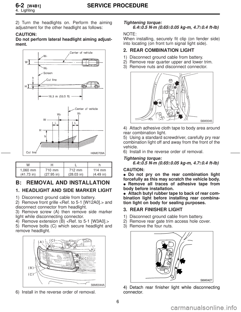
2) Turn the headlights on. Perform the aiming
adjustment for the other headlight as follows:
CAUTION:
Do not perform lateral headlight aiming adjust-
ment.
H6M0709A
WH L h
1,060 mm
(41.73 in)710 mm
(27.95 in)712 mm
(28.03 in)11 4 m m
(4.49 in)
B: REMOVAL AND INSTALLATION
1. HEADLIGHT AND SIDE MARKER LIGHT
1) Disconnect ground cable from battery.
2) Remove front grille
disconnect connector from headlight.
3) Remove screw (A) then remove side marker
light while disconnecting connector.
4) Remove extension (B)
5) Remove bolts (C) which secure headlight and
remove headlight.
S6M0044A
6) Install in the reverse order of removal.
Tightening torque:
6.4
±0.5 N´m (0.65±0.05 kg-m, 4.7±0.4 ft-lb)
NOTE:
When installing, securely fit clip (on fender side)
into locating (on front turn signal light side).
2. REAR COMBINATION LIGHT
1) Disconnect ground cable from battery.
2) Remove rear quarter upper and lower trim.
3) Remove nuts and disconnect connector.
S6M0045
4) Attach adhesive cloth tape to body area around
rear combination light.
5) Using a standard screwdriver, carefully pry rear
combination light off and away from the front of the
vehicle.
6) Install in the reverse order of removal.
Tightening torque:
6.4
±0.5 N´m (0.65±0.05 kg-m, 4.7±0.4 ft-lb)
CAUTION:
IDo not pry on the rear combination light
forcefully as this may scratch the vehicle body.
IRemove all traces of adhesive tape from
body before installation.
IAttach butyl rubber tape to back of rear com-
bination light before installing rear combina-
tion light on body for sealing purposes.
3. REAR FINISHER LIGHT
1) Disconnect ground cable from battery.
2) Remove rear gate trim access hole cover.
3) Remove the four nuts.
S6M0427
4) Detach rear finisher light while disconnecting
connector.
6
6-2[W4B1]SERVICE PROCEDURE
4. Lighting