Page 92 of 558
ENGINE – Crankshaft and Flywheel11-67
CRANKSHAFT AND FLYWHEEL
REMOVAL AND INSTALLATION
Apply engine oil to all
moving parts before
installation.
1 2
3
4 56
78 910 11 12
13 1415
25 Nm + 90�11 Nm132 Nm
9 Nm
11 Nm
32 Nm11 Nm
Removal steps
1. Flywheel bolt
2. Flywheel
3. Rear plate
4. Bell housing cover
�E�5. Oil seal case
�D�6. Oil seal
�C�7. Beam bearing cap bolt
�C�8. Beam bearing cap�B�9. Crankshaft bearing lower
10. Crankshaft
�B�11. Crankshaft bearing upper
�A�12. Crankshaft thrust bearing
13. Check valve
14. Oil jet
15. Cylinder block
Page 93 of 558
ENGINE – Crankshaft and Flywheel11-68
INSTALLATION SERVICE POINTS
�A�CRANKSHAFT THRUST BEARING INSTALLATION
(1) Install the two thrust bearing in the number 3 bearing
bore in the cylinder block. For easier installation, apply
engine oil to the bearings; this will help hold them in
position.
(2) The thrust bearings must be installed with their groove
side toward the crankshaft web.
�B�CRANKSHAFT BEARING INSTALLATION
(1) From the following table, select a bearing whose size
is appropriate for the crankshaft journal outside diameter.
Groove
Identification color of crankshaft journal
Bearing bore size
identification mark
Bearing bore
identification
mark
Cylinder inner
diameter size
mark
Rear face of
cylinder block Bottom of
cylinder block No. 1 No. 2No. 3
No. 4No. 5
Page 94 of 558

ENGINE – Crankshaft and Flywheel11-69
Crankshaft journal outside diameterCylinder block bearing boreCrankshaft bearing
Identification colorSize mmIdentification markIdentification mark or color
Yellow56.994 – 57.00000 or Black
11 or Green
22 or Yellow
None56.988 – 56.99401 or Green
12 or Yellow
23 or None
White56.982 – 56.98802 or Yellow
13 or None
24 or Blue
For example, if the crankshaft journal outside diameter
ID color is “yellow” and cylinder block bearing bore ID
mark is “1”, select a bearing whose ID mark is “1”.
If there is no ID color paint on the crankshaft, measure
the journal outside diameter and select a bearing
appropriate for the measured value.
(2) Install the bearings having an oil groove to the cylinder
block.
(3) Install the bearings having no oil groove to the bearing
cap.
�C�BEARING CAP / BEARING CAP BOLT
INSTALLATION
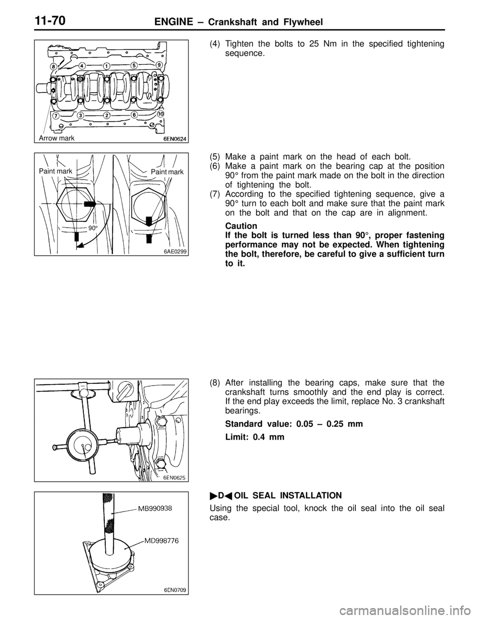
(1) Install the bearing caps so the arrow points to the timing
belt side.
(2) Before installing the bearing cap bolts, check that the
shank length of each bolt meets the limit. If the limit is
exceeded, replace the bolt.
Limit: Max. 71.1 mm
(3) Apply engine oil to the threaded portion and bearing
surface of the bolt.Crankshaft bearing size
identification mark or color
Identification
mark or color
UpperGroove
Lower
9EN0477
Shank length
Page 95 of 558

ENGINE – Crankshaft and Flywheel11-70
(4) Tighten the bolts to 25 Nm in the specified tightening
sequence.
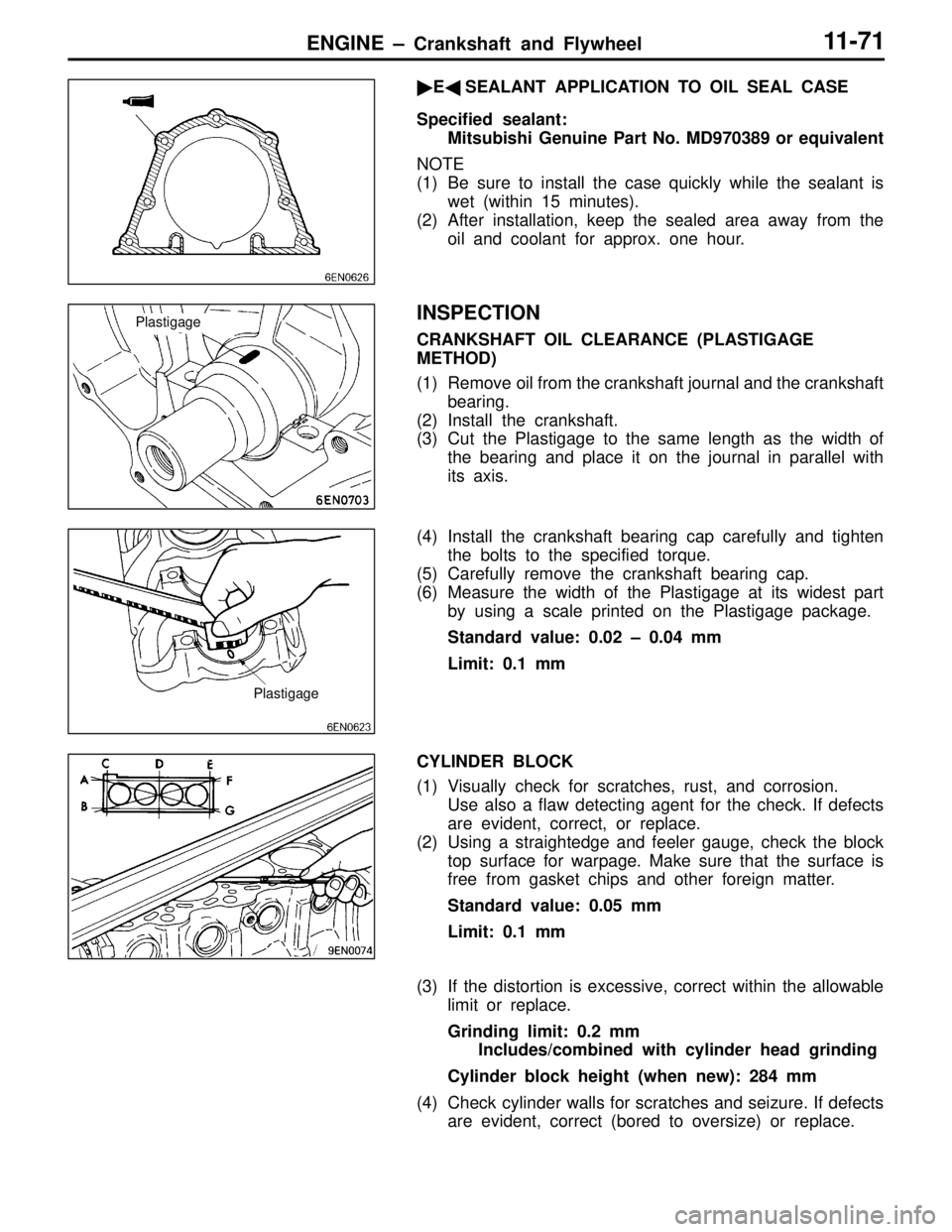
(5) Make a paint mark on the head of each bolt.
(6) Make a paint mark on the bearing cap at the position
90° from the paint mark made on the bolt in the direction
of tightening the bolt.
(7) According to the specified tightening sequence, give a
90° turn to each bolt and make sure that the paint mark
on the bolt and that on the cap are in alignment.
Caution
If the bolt is turned less than 90°, proper fastening
performance may not be expected. When tightening
the bolt, therefore, be careful to give a sufficient turn
to it.
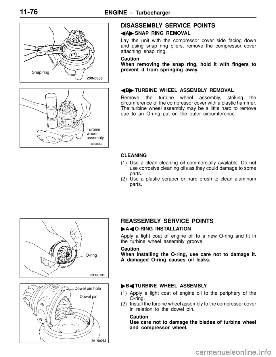
(8) After installing the bearing caps, make sure that the
crankshaft turns smoothly and the end play is correct.
If the end play exceeds the limit, replace No. 3 crankshaft
bearings.
Standard value: 0.05 – 0.25 mm
Limit: 0.4 mm
�D�OIL SEAL INSTALLATION
Using the special tool, knock the oil seal into the oil seal
case.
Arrow mark
6AE0299
Paint markPaint mark
90°
Page 96 of 558

ENGINE – Crankshaft and Flywheel11-71
�E�SEALANT APPLICATION TO OIL SEAL CASE
Specified sealant:
Mitsubishi Genuine Part No. MD970389 or equivalent
NOTE
(1) Be sure to install the case quickly while the sealant is
wet (within 15 minutes).
(2) After installation, keep the sealed area away from the
oil and coolant for approx. one hour.
INSPECTION
CRANKSHAFT OIL CLEARANCE (PLASTIGAGE
METHOD)
(1) Remove oil from the crankshaft journal and the crankshaft
bearing.
(2) Install the crankshaft.
(3) Cut the Plastigage to the same length as the width of
the bearing and place it on the journal in parallel with
its axis.
(4) Install the crankshaft bearing cap carefully and tighten
the bolts to the specified torque.
(5) Carefully remove the crankshaft bearing cap.
(6) Measure the width of the Plastigage at its widest part
by using a scale printed on the Plastigage package.
Standard value: 0.02 – 0.04 mm
Limit: 0.1 mm
CYLINDER BLOCK
(1) Visually check for scratches, rust, and corrosion.
Use also a flaw detecting agent for the check. If defects
are evident, correct, or replace.
(2) Using a straightedge and feeler gauge, check the block
top surface for warpage. Make sure that the surface is
free from gasket chips and other foreign matter.
Standard value: 0.05 mm
Limit: 0.1 mm
(3) If the distortion is excessive, correct within the allowable
limit or replace.
Grinding limit: 0.2 mm
Includes/combined with cylinder head grinding
Cylinder block height (when new): 284 mm
(4) Check cylinder walls for scratches and seizure. If defects
are evident, correct (bored to oversize) or replace.
Plastigage
Plastigage
Page 101 of 558

ENGINE – Turbocharger11-76
DISASSEMBLY SERVICE POINTS
�A�SNAP RING REMOVAL
Lay the unit with the compressor cover side facing down
and using snap ring pliers, remove the compressor cover
attaching snap ring.
Caution
When removing the snap ring, hold it with fingers to
prevent it from springing away.
�B�TURBINE WHEEL ASSEMBLY REMOVAL
Remove the turbine wheel assembly, striking the
circumference of the compressor cover with a plastic hammer.
The turbine wheel assembly may be a little hard to remove
due to an O-ring put on the outer circumference.
CLEANING
(1) Use a clean cleaning oil commercially available. Do not
use corrosive cleaning oils as they could damage to some
parts.
(2) Use a plastic scraper or hard brush to clean aluminum
parts.
REASSEMBLY SERVICE POINTS
�A�O-RING INSTALLATION
Apply a light coat of engine oil to a new O-ring and fit in
the turbine wheel assembly groove.
Caution
When installing the O-ring, use care not to damage it.
A damaged O-ring causes oil leaks.
�B�TURBINE WHEEL ASSEMBLY
(1) Apply a light coat of engine oil to the periphery of the
O-ring.
(2) Install the turbine wheel assembly to the compressor cover
in relation to the dowel pin.
Caution
Use care not to damage the blades of turbine wheel
and compressor wheel.
Snap ring
Turbine
wheel
assembly
O-ring
Dowel pin hole
Dowel pin
Page 103 of 558
ENGINE – Turbocharger11-78
COMPRESSOR COVER
Check the compressor cover for traces of contact with the
compressor wheel and other damage.
TURBINE WHEEL ASSEMBLY
(1) Check the turbine and compressor wheel blades for bend,
burr, damage, corrosion and traces of contact on the
back side and replace if defective.
(2) Check the oil passage of the turbine wheel assembly
for deposit and clogging.
(3) In the case of water cooled type, check also the water
passage for deposit and clogging.
(4) Check the turbine wheel and compressor wheel for light
and smooth turning.Oil passage
Turbine wheel
Compressor
wheelWater passage
Page 105 of 558

ENGINE – Alternator11-80
DISASSEMBLY SERVICE POINTS
�A�FRONT BRACKET ASSEMBLY REMOVAL
Insert a flat tip screwdrivers or the like in the clearance between
the front bracket assembly and stator core, to pry open and
separate the stator and front bracket.
Caution
Do not insert the screwdriver too far, or the stator coil
gets damaged.
�B�ALTERNATOR PULLEY REMOVAL
Face pulley side upward, fix the rotor with a work bench
and remove the pulley.
Caution
Use care not to damage the rotor.
�C�STATOR / REGULATOR ASSEMBLY REMOVAL
(1) Unsolder the stator with a soldering iron (180 to 250
W). Complete this work within four seconds not to transfer
heat to the diode.
(2) When removing rectifier from the regulator assembly,
remove the soldered sections to rectifier.
Caution
1. Use care to make sure that the heat of the soldering
iron is not transmitted to the diodes for a long
period.
2. Use care that no undue force is exerted to the
lead wires of the diodes.
REASSEMBLY SERVICE POINTS
�A�REGULATOR ASSEMBLY INSTALLATION
After installing the regulator assembly, insert a wire into the
hole provided on the rear bracket while pressing in the brush
to fix the brush.
NOTE
The brush is fixed when a wire is inserted, making rotor
installation easier.
Soldered
Rear bracket
Brush
WireWire