Page 94 of 558

ENGINE – Crankshaft and Flywheel11-69
Crankshaft journal outside diameterCylinder block bearing boreCrankshaft bearing
Identification colorSize mmIdentification markIdentification mark or color
Yellow56.994 – 57.00000 or Black
11 or Green
22 or Yellow
None56.988 – 56.99401 or Green
12 or Yellow
23 or None
White56.982 – 56.98802 or Yellow
13 or None
24 or Blue
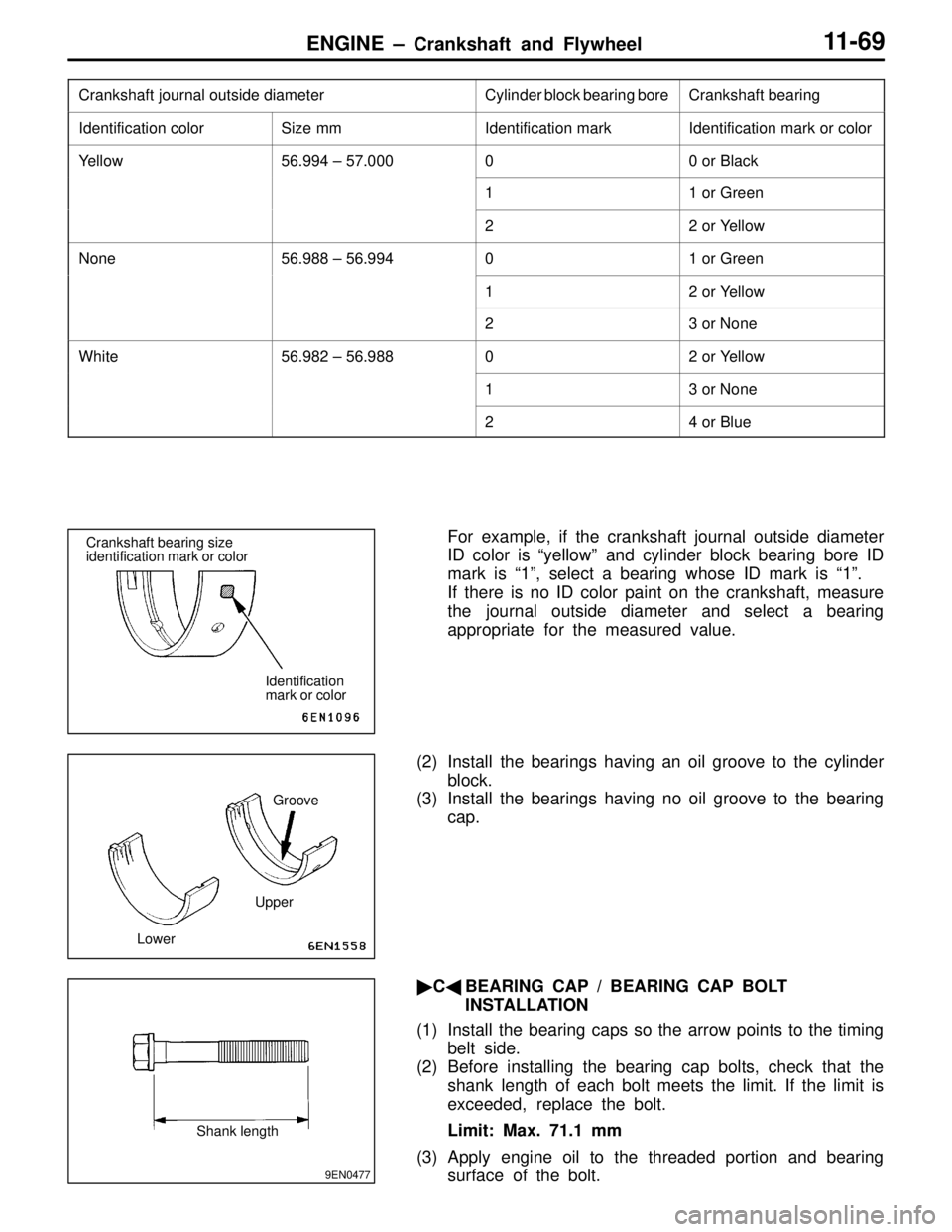
For example, if the crankshaft journal outside diameter
ID color is “yellow” and cylinder block bearing bore ID
mark is “1”, select a bearing whose ID mark is “1”.
If there is no ID color paint on the crankshaft, measure
the journal outside diameter and select a bearing
appropriate for the measured value.
(2) Install the bearings having an oil groove to the cylinder
block.
(3) Install the bearings having no oil groove to the bearing
cap.
�C�BEARING CAP / BEARING CAP BOLT
INSTALLATION
(1) Install the bearing caps so the arrow points to the timing
belt side.
(2) Before installing the bearing cap bolts, check that the
shank length of each bolt meets the limit. If the limit is
exceeded, replace the bolt.
Limit: Max. 71.1 mm
(3) Apply engine oil to the threaded portion and bearing
surface of the bolt.Crankshaft bearing size
identification mark or color
Identification
mark or color
UpperGroove
Lower
9EN0477
Shank length
Page 96 of 558

ENGINE – Crankshaft and Flywheel11-71
�E�SEALANT APPLICATION TO OIL SEAL CASE
Specified sealant:
Mitsubishi Genuine Part No. MD970389 or equivalent
NOTE
(1) Be sure to install the case quickly while the sealant is
wet (within 15 minutes).
(2) After installation, keep the sealed area away from the
oil and coolant for approx. one hour.
INSPECTION
CRANKSHAFT OIL CLEARANCE (PLASTIGAGE
METHOD)
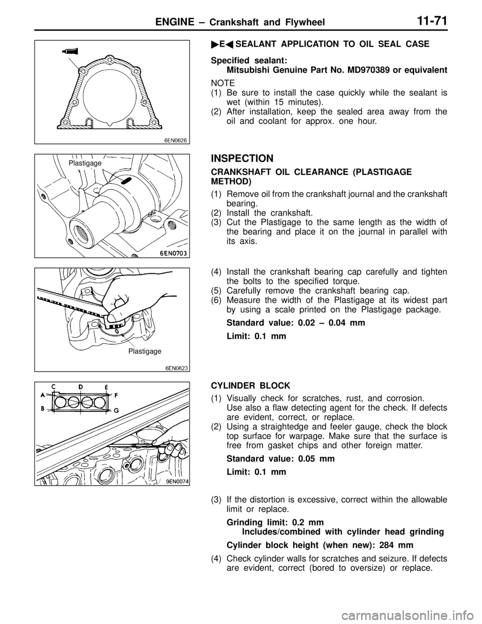
(1) Remove oil from the crankshaft journal and the crankshaft
bearing.
(2) Install the crankshaft.
(3) Cut the Plastigage to the same length as the width of
the bearing and place it on the journal in parallel with
its axis.
(4) Install the crankshaft bearing cap carefully and tighten
the bolts to the specified torque.
(5) Carefully remove the crankshaft bearing cap.
(6) Measure the width of the Plastigage at its widest part
by using a scale printed on the Plastigage package.
Standard value: 0.02 – 0.04 mm
Limit: 0.1 mm
CYLINDER BLOCK
(1) Visually check for scratches, rust, and corrosion.
Use also a flaw detecting agent for the check. If defects
are evident, correct, or replace.
(2) Using a straightedge and feeler gauge, check the block
top surface for warpage. Make sure that the surface is
free from gasket chips and other foreign matter.
Standard value: 0.05 mm
Limit: 0.1 mm
(3) If the distortion is excessive, correct within the allowable
limit or replace.
Grinding limit: 0.2 mm
Includes/combined with cylinder head grinding
Cylinder block height (when new): 284 mm
(4) Check cylinder walls for scratches and seizure. If defects
are evident, correct (bored to oversize) or replace.
Plastigage
Plastigage
Page 103 of 558
ENGINE – Turbocharger11-78
COMPRESSOR COVER
Check the compressor cover for traces of contact with the
compressor wheel and other damage.
TURBINE WHEEL ASSEMBLY
(1) Check the turbine and compressor wheel blades for bend,
burr, damage, corrosion and traces of contact on the
back side and replace if defective.
(2) Check the oil passage of the turbine wheel assembly
for deposit and clogging.
(3) In the case of water cooled type, check also the water
passage for deposit and clogging.
(4) Check the turbine wheel and compressor wheel for light
and smooth turning.Oil passage
Turbine wheel
Compressor
wheelWater passage
Page 106 of 558
ENGINE – Alternator11-81
�B�ROTOR INSTALLATION
After installing the rotor, remove the wire used to fix the brush.
INSPECTION
ROTOR CHECK
(1) Check the continuity between the rotor coil slip rings,
and replace the rotor if the resistance value is not at
the standard value.
Standard value: 3 – 5 Ω
(2) Check the continuity between the slip ring and core, and
if there is continuity, replace the rotor.
STATOR CHECK
(1) Check the continuity between the coil leads, and if there
is continuity, replace the stator.
(2) Check the continuity between the coil and core, and if
there is continuity, replace the stator.
Wire
Page 107 of 558

ENGINE – Alternator11-82
RECTIFIERS CHECK
(1) Inspect the (+) heat sink by checking the continuity
between the (+) heat sink and stator coil lead wire
connection terminal using a tester probe.
If there is a continuity at both, the diode is short circuited,
so replace the rectifier.
(2) Inspect the (–) heat sink by checking the continuity
between the (–) heat sink and stator coil lead wire
connection terminal using a tester probe.
If there is a continuity at both, the diode is short circuited,
so replace the rectifier.
(3) Check the diode trio by connecting an ohmmeter to both
ends of each diode and check the continuity of the three
diodes.
If there is a continuity at both ends, or if there is no
continuity, the diode is damaged so replace the recitifier.
BRUSH CHECK
(1) Measure the length of the brush protrusion shown in the
illustration, and replace the brush if the measured value
is below the limit value.
Limit: 2 mm or less
(2) The brush can be removed if the solder of the brush
lead wire is removed.
(3) When installing a new brush, insert the brush into the
holder as shown in the illustration, and then solder the
lead wires.
Protrusion
length
Soldered
Page 111 of 558

ENGINE – Starter Motor11-86
OVERRUNING CLUTCH CHECK
(1) While holding clutch housing, rotate the pinion. Drive
pinion should rotate smoothly in one direction, but should
not rotate in opposite direction. If clutch does not function
properly, replace overrunnig clutch assembly.
(2) Inspect pinion for wear or burrs. If pinion is worn or burred,
replace overrunning clutch assembly. If pinion is damaged,
also inspect ring gear for wear or burrs.
FRONT AND REAR BRACKET BUSHING CHECK
Inspect bushing for wear or burrs. If bushing is worn or burred,
replace front bracket assembly or rear bracket assembly.
BRUSH AND SPRING REPLACEMENT
(1) Brushes that are worn beyond wear limit line, or oil-soaked,
should be replaced.
(2) When replacing ground brush, slide the brush from brush
holder by prying retaining spring back.
ARMATURE TEST
ARMATURE COIL SHORT-CIRCUIT TEST
(1) Place armature in a growler.
(2) Hold a thin steel blade parallel and just above while rotating
armature slowly in growler. A shorted armature will cause
blade to vibrate and be attracted to the core. Replace
shorted armature.
ARMATURE COIL EARTH TEST
Check the insulation between each commutator segment and
armature coil core.
If there is no continuity, the insulation is in order.
Free
Lock
Wear limit line
Growler
Page 112 of 558
ENGINE – Starter Motor11-87
ARMATURE COIL OPEN-CIRCUIT INSPECTION
Check the continuity between segments. If there is continuity,
the coil is in order.
Page 115 of 558

MPI – General13-3
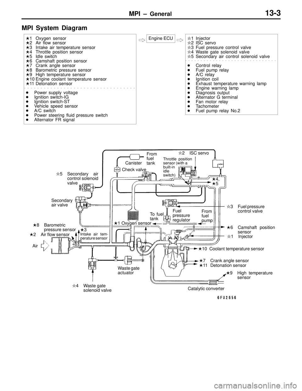
MPI System Diagram
�1 Injector
�2 ISC servo
�3 Fuel pressure control valve
�4 Waste gate solenoid valve
�5 Secondary air control solenoid valve
�Control relay
�Fuel pump relay
�A/C relay
�Ignition coil
�Exhaust temperature warning lamp
�Engine warning lamp
�Diagnosis output
�Alternator G terminal
�Fan motor relay
�Tachometer
�Fuel pump relay No.2 �1 Oxygen sensor
�2 Air flow sensor
�3 Intake air temperature sensor
�4 Throttle position sensor
�5 Idle switch
�6 Camshaft position sensor
�7 Crank angle sensor
�8 Barometric pressure sensor
�9 High temperature sensor
�10 Engine coolant temperature sensor
�11 Detonation sensor
�Power supply voltage
�Ignition switch-IG
�Ignition switch-ST
�Vehicle speed sensor
�A/C switch
�Power steering fluid pressure switch
�Alternator FR signalEngine ECU
�1 Oxygen sensor
�2 Air flow sensor�3
Intake air tem-
perature sensor
�4,
�5
�6 Camshaft position
sensor
�7 Crank angle sensor �8 Barometric
pressure sensor
�9 High temperature
sensor �10 Coolant temperature sensor
�11 Detonation sensor�1 Injector �2 ISC servo
�3 Fuel pressure
control valve
�4 Waste gate
solenoid valve �5 Secondary air
control solenoid
valveCanister
Check valveFrom
fuel
tank
Throttle position
sensor (with a
built-in
idle
switch)
Secondary
air valve
AirTo fuel
tankFuel
pressure
regulatorFrom
fuel
pump
Waste gate
actuator
Catalytic converter