Page 354 of 558

CHASSIS ELECTRICAL – Ignition Switch and Immobilizer System54-16
INSPECTION CHART FOR TROUBLE SYMPTOMS
Trouble symptomInspection procedure No.Reference page
Communication with MUT-II is impossible.154-16
ID code cannot be registered using the MUT-II.254-17
Engine does not start (Cranking but no initial combustion).354-17
Malfunction of the immobilizer-ECU power source and earth circuit454-18
INSPECTION PROCEDURE FOR TROUBLE SYMPTOMS
Inspection Procedure 1
Communication with MUT-II is impossible.
Probable cause
The cause is probably that a malfunction of the diagnosis line or the immobilizer-ECU
is not functioning.�Malfunction of the diagnosis line
�Malfunction of harness or connector
�Malfunction of the immobilizer-ECU
Can the MUT-II communicate with the
engine-ECU?NOCheck the following connectors.
B-100, B-22NG
Repair
YES
Check the immobilizer-ECU connector
B-100.
(Short-circuited harness wire between
terminal No. 13 and No. 14)NG
Repair
OK
Check trouble symptoms.
NG
Check the harness wire between immo-
bilizer-ECU and diagnosis connector.NG
Repair
OK
Check the immobilizer-ECU power sup-
ply and earth circuit. (Refer to INSPEC-
TION PROCEDURE 4.)
OK
Check trouble symptoms.NGReplace the immobilizer-ECU.
OK
Page 355 of 558

CHASSIS ELECTRICAL – Ignition Switch and Immobilizer SystemCHASSIS ELECTRICAL – Ignition Switch and Immobilizer System54-17
Inspection Procedure 2
ID code cannot be registered using the MUT-II.
Probable cause
The cause is probably that there is no ID code registered in the immobilizer-ECU,
or there is a malfunction of the immobilizer-ECU.�Malfunction of the transponder
�Malfunction of the ignition key ring antenna
�Malfunction of harness or connector
�Malfunction of the immobilizer-ECU
No ignition key can be registered.NOReplace the ignition key that cannot be
registered.Re-register the ID code.
(Refer to P.54-21.)
YES
Is a diagnosis code output?NOTo INSPECTION CHART FOR DIAG-
NOSIS CODE (Refer to P.54-13.)
YES
Check the immobilizer-ECU power
source and earth circuit. (Refer to
INSPECTION PROCEDURE 4.)OKCheck trouble symptoms.NGReplace the immobilizer-ECU.
Inspection Procedure 3
Engine does not start (cranking but no initial combustion).
Probable cause
If the fuel injectors are not operating, there might be a problem with the MPI system
in addition to a malfunction of the immobilizer system.
It is normal for this to occur if an attempt is made to start the engine using a key
that has not been properly registered.�Malfunction of the MPI system
�Malfunction of the immobilizer-ECU
Is a diagnosis code output from the
immobilizer-ECU?NOTo INSPECTION CHART FOR DIAG-
NOSIS CODE (Refer to P.54-13.)
YES
Is a diagnosis code output from the
engine-ECU?NORefer to GROUP 13A – Troubleshoot-
ing.
YES
To inspection procedure for when there
is no initial combustion. (Refer to
GROUP 13A – Troubleshooting.)
OK
Check trouble symptoms.
NG
Check the immobilizer-ECU power sup-
ply and earth circuit (Refer to INSPEC-
TION PROCEDURE 4.)OKCheck trouble symptoms.NGReplace the immobilizer-ECU.
Page 356 of 558

CHASSIS ELECTRICAL – Ignition Switch and Immobilizer System54-18
Inspection Procedure 4
Malfunction of the immobilizer-ECU power supply and earth circuit
Measure at the immobilizer-ECU con-
nector B-100.
�Disconnect the connector and
measure at the harness side.
(1) Voltage between 2 and body earth
(Ignition switch: ON)
OK: System voltage
(2) Voltage between 1 and body earth
OK: System voltage
(3) Continuity between 8 and body earth
OK: Continuity(1) NGCheck the following connectors:
B-76, B-74, B-100NG
Repair
OK
Check trouble symptoms.
NG
Check the fuse and the harness wire
between the ignition switch (IG) and
immobilizer-ECU.NG
OK
Check trouble symptoms.NGCheck the ignition switch.
(Refer to P.54-20.)
(2) NG
Check the following connectors:
B-65, B-100NG
Repair
OK
Check trouble symptoms.NGCheck the harness wire between the
immobilizer-ECU and the engine control
relay, and repair if necessary.
(3) NG
Check the following connectors.
B-50, B-100NG
Repair
OK
Check trouble symptoms.NGCheck the harness wire between the
immobilizer-ECU and body earth, and
repair if necessary. Repair
CHECK AT IMMOBILIZER-ECU
TERMINAL VOLTAGE CHECK CHART
Terminal No.SignalChecking requirementsTerminal voltage
1Immobilizer-ECU power supplyIgnition switch: ONSystem voltage
2Ignition switch-IGIgnition switch: OFF0V
Ignition switch: ONSystem voltage
8Immobilizer-ECU earthAlways0V
Page 359 of 558

CHASSIS ELECTRICAL – Ignition Switch and Immobilizer System54-21
ID CODE REGISTRATION METHOD
If using an ignition key that has just been newly purchased,
or if the immobilizer-ECU has been replaced, you will need
to register the ID codes for each ignition key being used
into the immobilizer-ECU. (A maximum of eight different ID
codes can be registered.)
Moreover, when the immobilizer-ECU has been replaced, you
will need to use the MUT-II to register the password that
the user specifies into the immobilizer-ECU. (Refer to the
MUT-II instruction manual for instructions on using the MUT-II.)
Caution
If registering of the ID codes is carried out all
previously-registered codes will be erased. Accordingly,
you should have ready all of the ignition keys that have
already been registered.
1. Connect the MUT-II to the diagnosis connector.
Caution
Turn the ignition switch off before connecting or
disconnecting the MUT-II.
2. Check that the diagnosis code No.54 is not displayed
for MPI system. If the code is displayed, carry out
troubleshooting before proceeding to the next step. (Refer
to GROUP 13A – Troubleshooting).
3. Use the ignition key that is to be registered to turn the
ignition switch to the ON position.
4. Use the MUT-II to register the ID code. If you are
registering two or more codes, use the next key to be
registered to turn the ignition switch to the ON position
without disconnecting the MUT-II.
5. Disconnect the MUT-II. This completes the registration
operation.
6. Check that the engine can be started by each one of
the ignition keys.
7. Check that the diagnosis code No.54 is not displayed
for MPI system. If the code is displayed, erase it. (Refer
to GROUP 13A – Troubleshooting).
MUT-II
Page 361 of 558
CHASSIS ELECTRICAL – Combination Meters54-23
SEALANT
ItemsSpecified sealantRemark
Engine coolant temperature gauge
unit threaded portion3M Adhesive nut locking No. 4171 or
equivalentDrying sealant
SPECIAL TOOLS
ToolNumberNameUse
A
B
C
D
MB991223
A: MB991219
B: MB991220
C: MB991221
D: MB991222Harness set
A: Test harness
B: LED harness
C: LED harness
adapter
D: ProbeFuel gauge simple check
A: Connector pin contact pressure check
B, C: Power circuit check
D: Commercial tester connection
Page 362 of 558

CHASSIS ELECTRICAL – Combination Meters54-24
TROUBLESHOOTING
INSPECTION CHART FOR TROUBLE SYMPTOMS
Trouble symptomInspection
procedureReference
page
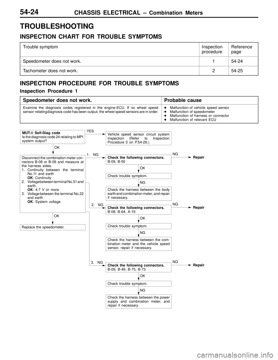
Speedometer does not work.154-24
Tachometer does not work.254-25
INSPECTION PROCEDURE FOR TROUBLE SYMPTOMS
Inspection Procedure 1
Speedometer does not work.
Probable cause
Examine the diagnosis codes registered in the engine-ECU. If no wheel speed
sensor-relating diagnosis code has been output, the wheel speed sensors are in order.�Malfunction of vehicle speed sensor
�Malfunction of speedometer
�Malfunction of harness or connector
�Malfunction of relevant ECU
Disconnect the combination meter con-
nectors B-08 or B-09 and measure at
the harness sides.
1. Continuity between the terminal
No.11 and earth
OK: Continuity
2. Voltage between terminal No.51 and
earth.
OK: 4.7 V or more
3. Voltage between the terminal No.22
and earth
OK: System voltage1. NG
OK
Replace the speedometer.YES
Vehicle speed sensor circuit system
inspection (Refer to Inspection
Procedure 3 on P.54-26.)
OK
Check the following connectors.
B-09, B-50NG
Repair
OK
Check trouble symptom.
Check the harness between the body
earth and combination meter, and repair
if necessary.NG
2. NGCheck the following connectors.
B-08, B-64, A-19NG
Repair
OK
Check trouble symptom.
Check the harness between the com-
bination meter and the vehicle speed
sensor, repair if necessary.NG
3. NGCheck the following connectors.
B-09, B-49, B-75, B-73NG
Repair
OK
Check trouble symptom.
Check the harness between the power
supply and combination meter, and
repair if necessary.NG
MUT-II Self-Diag code
Is the diagnosis code 24 relating to MPI
system output?
Page 363 of 558

CHASSIS ELECTRICAL – Combination Meters54-25
Inspection Procedure 2
Tachometer does not work.
Probable cause
The ignition signal may not be input from the engine, or there may be a malfunction
in the power supply or earth circuit.�Malfunction of tachometer
�Malfunction of harness or connector
Disconnect the combination meter con-
nector B-08 and measure at the harness
sides.
1. Measure the voltage between
terminal No.33 and earth.
OK: 5 V
2. Continuity between the terminal
No.34 and earth
OK: Continuity
3. Voltage between the terminal No.42
and earth
OK: System voltage1. NGCheck the following connectors.
B-08, A-36, B-61, B-64, A-41, A-109NG
Repair
OK
Check trouble symptom.NGCheck the harness between the engine-
ECU and combination meter, and repair
if necessary.
2. NGCheck the following connectors.
B-08, B-50, B-64, A-41NG
Repair
OK
Check trouble symptom.NGCheck the harness between the com-
bination meter and the body earth, and
repair if necessary. OK
Replace the tachometer.
3. NG
Check the following connectors.
B-08, B-75, B-76NG
Repair
OK
Check trouble symptom.NGCheck the harness between the power
supply and combination meter, and
repair if necessary.
YESRefer to Group 13 – Troubleshooting,
No. 44 Ignition coils and power
transistors.
OK
MUT-II Self-Diag code
Is the diagnosis code 44 relating to MPI
system output?
Page 364 of 558

CHASSIS ELECTRICAL – Combination Meters54-26
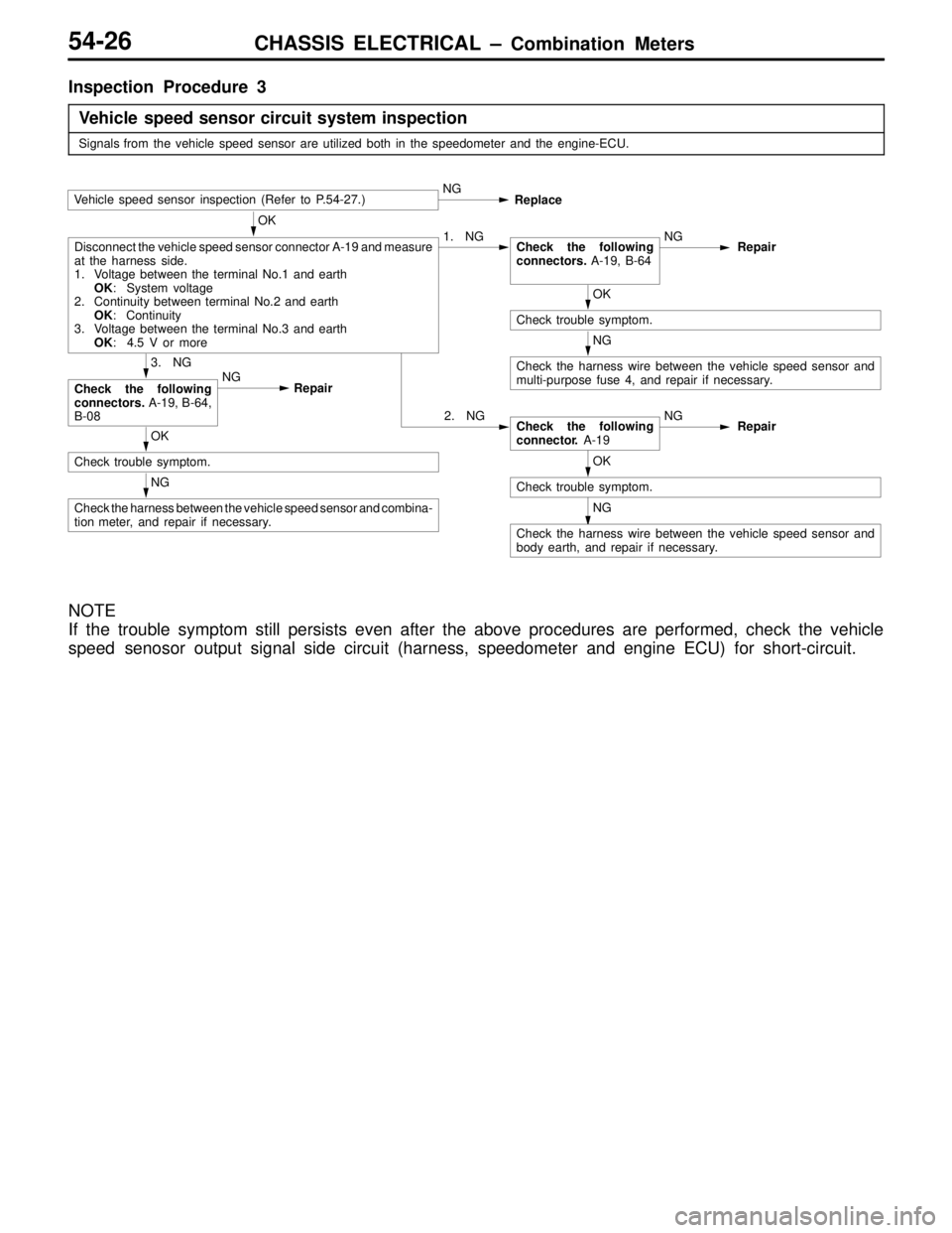
Inspection Procedure 3
Vehicle speed sensor circuit system inspection
Signals from the vehicle speed sensor are utilized both in the speedometer and the engine-ECU.
Vehicle speed sensor inspection (Refer to P.54-27.)NG
Replace
OK
Disconnect the vehicle speed sensor connector A-19 and measure
at the harness side.
1. Voltage between the terminal No.1 and earth
OK: System voltage
2. Continuity between terminal No.2 and earth
OK: Continuity
3. Voltage between the terminal No.3 and earth
OK: 4.5 V or more1. NGCheck the following
connectors. A-19, B-64NG
Repair
OK
Check trouble symptom.
NG
Check the harness wire between the vehicle speed sensor and
multi-purpose fuse 4, and repair if necessary.3. NG
Check the following
connectors. A-19, B-64,
B-08NG
Repair
2. NGCheck the following
connector. A-19NG
RepairOK
Check trouble symptom.
NG
Check the harness between the vehicle speed sensor and combina-
tion meter, and repair if necessary.OK
Check trouble symptom.
NG
Check the harness wire between the vehicle speed sensor and
body earth, and repair if necessary.
NOTE
If the trouble symptom still persists even after the above procedures are performed, check the vehicle
speed senosor output signal side circuit (harness, speedometer and engine ECU) for short-circuit.