Page 145 of 244
Roadside emergencies
Fuse rating
7.5 amp
10 amp
15 amp
20 amp
30 amp
30 amp fuse link
40 amp
60 amp fuse link
80 amp fuse link
100 amp fuse link
Color
brown
red
light blue
yellow
light green
pink
orange
yellow
black
blue
Relay
R 18
R 20
R 21
R 22
R 23
R 24
R 25
R 26ÒOne touchÓ switch
(driverÕs window)
Not used
Not used
Foglamps
Turn signals
Panic alarm Ð
driverÕs side
Panic alarm Ð
right-hand side
Not usedDriverÕs door
Ñ
Ñ
Module bracket
Steering column
Door lock module bracket
Ñ
Circuits switchedLocation
Standard fuse amperage ratings
and colors
3 amp violet
Auxiliary relays (outside of fuse boxes)
145
23MREen 4/13/99 3:42 PM Page 145
Page 146 of 244
Roadside emergencies
146
CHANGING TIRES
Park your vehicle in such a position
that neither the traffic nor you are
hindered or endangered when
changing the tire. Ensure that the
vehicle is on firm, level ground.
Secure your vehicle further by
blocking the wheels.
Activate the hazard lights.
Apply the parking brake and
engage first or reverse gear if the
vehicle has a manual transaxle or, if
the vehicle has an automatic
transaxle, select the P (Park)
position.
If parking on a slope is unavoidable,
block the wheels.
The temporary spare tire
The vehicle may have a high
pressure temporary spare tire. This
spare is smaller than a regular tire
and is designed for emergency use
only. This tire should be replaced
as soon as possible.
If you use the temporary
spare tire continuously or do
not follow these precautions, the
tire could fail, causing you to lose
control of the vehicle, possibly
injuring yourself or others.
23MREen 4/13/99 3:42 PM Page 146
Page 147 of 244
Roadside emergencies
147
80
MAX
km/h
When driving with a temporary
spare tire:
¥ Do not exceed the maximum
speed of 80 km/h (50 mph) and
only drive the shortest possible
distance.
¥ Do not exceed the permissible
gross weight of the vehicle.
¥ Do not install more than one
spare wheel on your vehicle at any
one time.
¥ Do not use snow chains on this
type of wheel.
¥ Do not drive through an
automatic car wash.
Spare tire location
The spare tire and tools are located
under the floor cover in the
luggage compartment.
50
MAX
mph
Removing the spare tire and
tools
1. Raise the rear of the floor cover
in the luggage compartment.
2. Completely unscrew the bolt and
remove the bolt and cup.
3. Lift out the spare wheel.
4. Unscrew the jack bolt and
remove jack.
5. Obtain jack handle, which is
located on the floor under the
spare wheel.
23MREen 4/13/99 3:42 PM Page 147
Page 148 of 244
Roadside emergencies
148
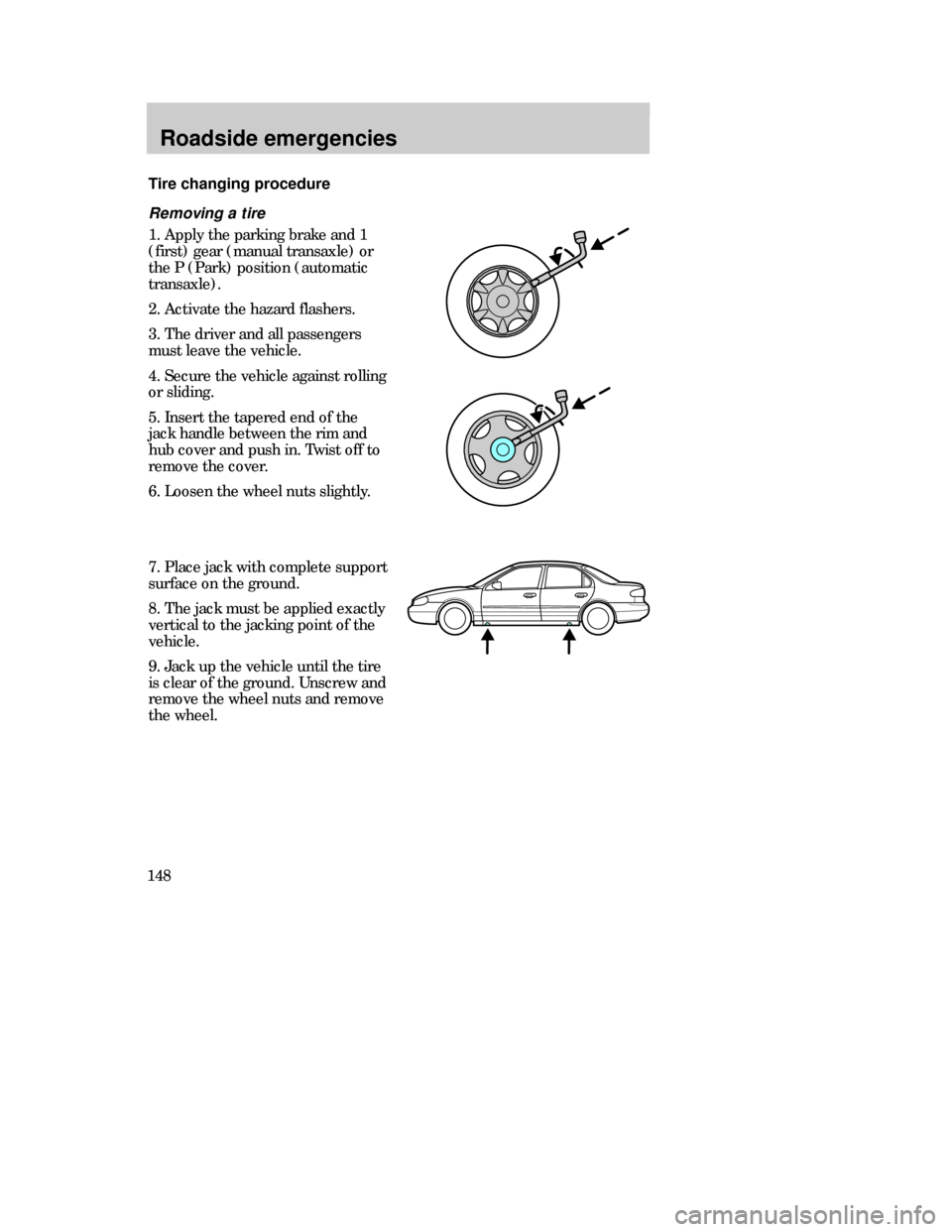
Removing a tire
1. Apply the parking brake and 1
(first) gear (manual transaxle) or
the P (Park) position (automatic
transaxle).
2. Activate the hazard flashers.
3. The driver and all passengers
must leave the vehicle.
4. Secure the vehicle against rolling
or sliding.
5. Insert the tapered end of the
jack handle between the rim and
hub cover and push in. Twist off to
remove the cover.
6. Loosen the wheel nuts slightly.
Tire changing procedure
7. Place jack with complete support
surface on the ground.
8. The jack must be applied exactly
vertical to the jacking point of the
vehicle.
9. Jack up the vehicle until the tire
is clear of the ground. Unscrew and
remove the wheel nuts and remove
the wheel.
23MREen 4/13/99 3:42 PM Page 148
Page 149 of 244
Roadside emergencies
149
Replacing a tire
1. Push the spare tire onto the
wheel studs.
2. Screw on the wheel nuts,
ensuring the tapered end of the
wheel nuts are facing the wheel,
and secure in a clockwise direction.
3. Lower the vehicle and remove
the jack by turning the handle
counterclockwise.
4. Fully tighten the wheel nuts in a
crosswise pattern.
5. Align the hub cap with the valve
and push firmly into position with
the ball of the hand.
6. Stow the jack and damaged tire
in the luggage compartment by
reversing the spare tire removal
instructions.
3
42 1
23MREen 4/13/99 3:42 PM Page 149
Page 150 of 244
Roadside emergencies
150
JUMP STARTING YOUR
VEHICLE
The gases around the
battery can explode if
exposed to flames, sparks, or lit
cigarettes. An explosion could
result in injury or vehicle damage.
Do not push start your
vehicle. You could damage
the catalytic converter.
Batteries contain sulfuric
acid which burns skin, eyes,
and clothing if contacted.
Do not attempt to push start
your vehicle. Automatic
transaxles do not have push-
start capability.
Preparing your vehicle
1.Use only a 12-volt supply to
start your vehicle.
2. Do not disconnect the battery of
the disabled vehicle as this could
damage the vehicles electrical
system.
23MREen 4/13/99 3:42 PM Page 150
Page 151 of 244
Roadside emergencies
151
3. Park the booster vehicle close to
the hood of the disabled vehicle,
making sure the two vehicles
do
not
touch. Set the parking brake
on both vehicles and stay clear of
the engine cooling fan and other
moving parts.
4. Check all battery terminals and
remove any excessive corrosion
before you attach the battery
cables. Ensure that vent caps are
tight and level.
5. Turn the heater fan on in both
vehicles to protect from any
electrical surges. Turn all other
accessories off.
Connecting the jumper cables
1. Connect the positive (+) booster
cable to the positive (+) terminal of
the discharge battery.
Note:In the illustrations,
Òlightning boltsÓ are used to
designate the assisting (boosting)
battery.
23MREen 4/13/99 3:42 PM Page 151
Page 152 of 244
Roadside emergencies
152
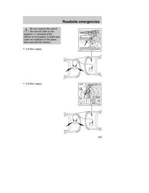
2. Connect the other end of the
positive (+) cable to the positive
(+) terminal of the assisting
battery.
3. Connect the negative (-) cable
to the negative (-) terminal of the
assisting battery.
4. Make the final connection of the
negative (-) cable to an exposed
metal part of the stalled vehicleÕs
engine, away from the battery and
the carburetor.
The preferred locations of an
exposed metal part (to ÒgroundÓ
the circuit) are the accessible
engine mount studs or an engine
lifting ÒeyeÓ.
Do notuse fuel lines,
engine rocker covers, or the intake
manifold as ÒgroundingÓ points.
23MREen 4/13/99 3:42 PM Page 152