Page 1186 of 1529

HEATING AND VENTILATION
REPAIRS 80-29
Heater matrix
$% 80.20.29
Remove
1.Remove heater assembly.
+ HEATING AND VENTILATION,
REPAIRS, Heater assembly - models with
air conditioning.
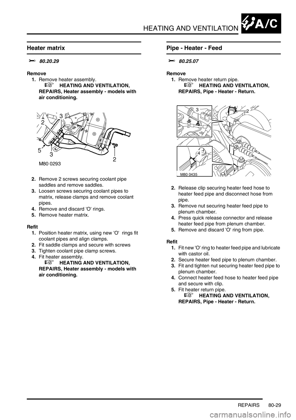
2.Remove 2 screws securing coolant pipe
saddles and remove saddles.
3.Loosen screws securing coolant pipes to
matrix, release clamps and remove coolant
pipes.
4.Remove and discard 'O' rings.
5.Remove heater matrix.
Refit
1.Position heater matrix, using new 'O' rings fit
coolant pipes and align clamps.
2.Fit saddle clamps and secure with screws
3.Tighten coolant pipe clamp screws.
4.Fit heater assembly.
+ HEATING AND VENTILATION,
REPAIRS, Heater assembly - models with
air conditioning.
Pipe - Heater - Feed
$% 80.25.07
Remove
1.Remove heater return pipe.
+ HEATING AND VENTILATION,
REPAIRS, Pipe - Heater - Return.
2.Release clip securing heater feed hose to
heater feed pipe and disconnect hose from
pipe.
3.Remove nut securing heater feed pipe to
plenum chamber.
4.Press quick release connector and release
heater feed pipe from plenum chamber.
5.Remove and discard 'O' ring from pipe.
Refit
1.Fit new 'O' ring to heater feed pipe and lubricate
with castor oil.
2.Secure heater feed pipe to plenum chamber.
3.Fit and tighten nut securing heater feed pipe to
plenum chamber.
4.Connect heater feed hose to heater feed pipe
and secure with clip.
5.Fit heater return pipe.
+ HEATING AND VENTILATION,
REPAIRS, Pipe - Heater - Return.
M80 0435
23
4
Page 1187 of 1529

HEATING AND VENTILATION
80-30REPAIRS
Pipe - Heater - Return
$% 80.25.12
Remove
1.Drain engine coolant.
+ COOLING SYSTEM - V8,
ADJUSTMENTS, Drain and refill.
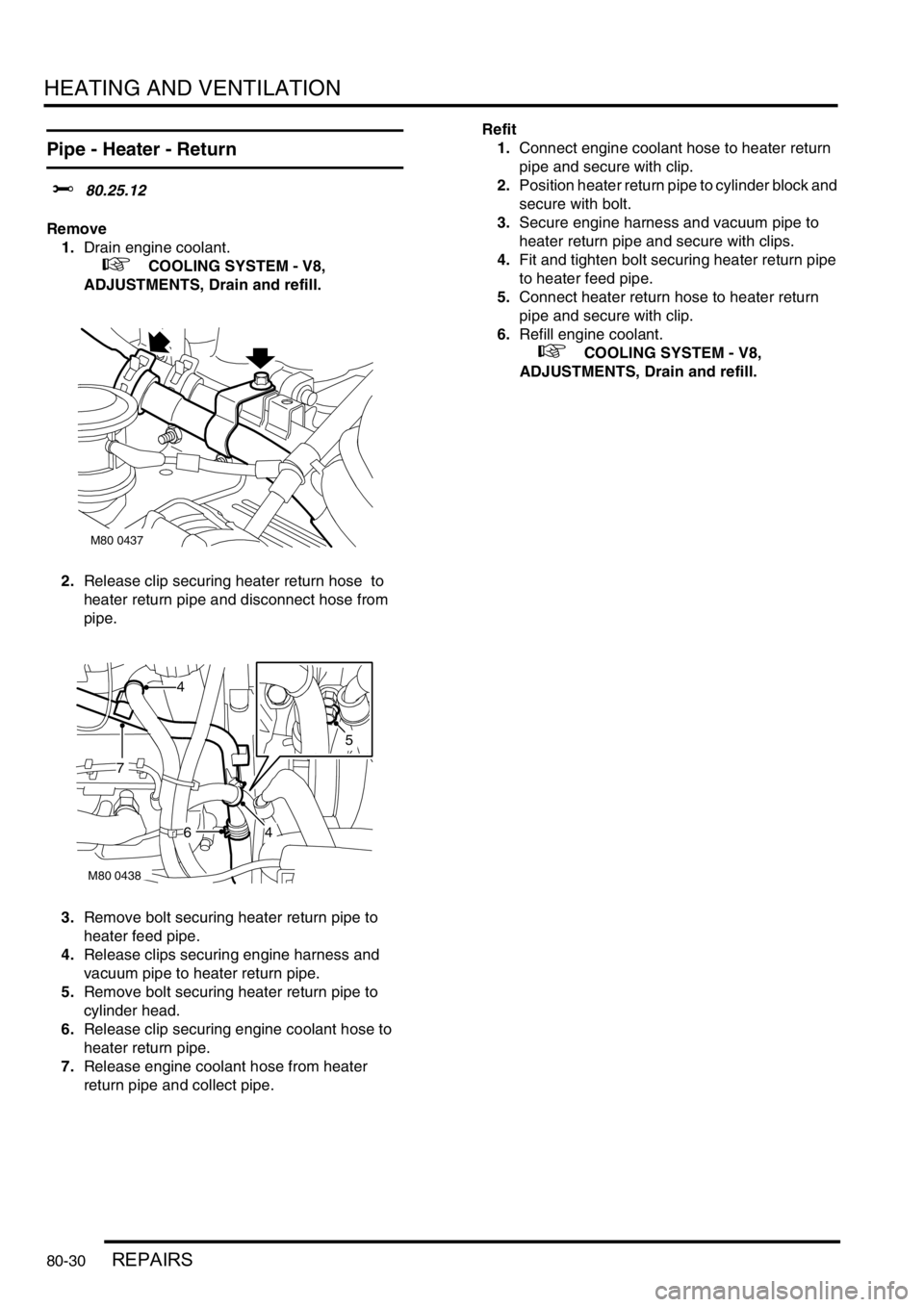
2.Release clip securing heater return hose to
heater return pipe and disconnect hose from
pipe.
3.Remove bolt securing heater return pipe to
heater feed pipe.
4.Release clips securing engine harness and
vacuum pipe to heater return pipe.
5.Remove bolt securing heater return pipe to
cylinder head.
6.Release clip securing engine coolant hose to
heater return pipe.
7.Release engine coolant hose from heater
return pipe and collect pipe.Refit
1.Connect engine coolant hose to heater return
pipe and secure with clip.
2.Position heater return pipe to cylinder block and
secure with bolt.
3.Secure engine harness and vacuum pipe to
heater return pipe and secure with clips.
4.Fit and tighten bolt securing heater return pipe
to heater feed pipe.
5.Connect heater return hose to heater return
pipe and secure with clip.
6.Refill engine coolant.
+ COOLING SYSTEM - V8,
ADJUSTMENTS, Drain and refill.
M80 0437
M80 0438
4
46
7
5
Page 1188 of 1529

HEATING AND VENTILATION
REPAIRS 80-31
Fuel burning heater - (FBH) - Td5
$% 80.40.01.99
Remove
1.Release fixings and remove battery cover.
2.Disconnect battery earth lead.
3.Clamp feed and return coolant hoses at FBH.
4.Position container to collect spillage.
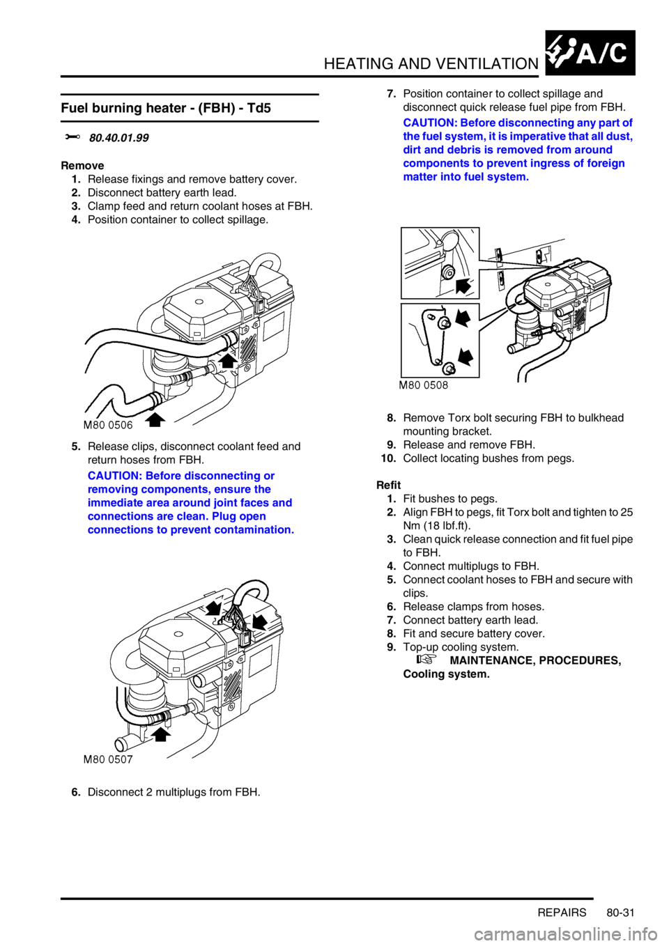
5.Release clips, disconnect coolant feed and
return hoses from FBH.
CAUTION: Before disconnecting or
removing components, ensure the
immediate area around joint faces and
connections are clean. Plug open
connections to prevent contamination.
6.Disconnect 2 multiplugs from FBH.7.Position container to collect spillage and
disconnect quick release fuel pipe from FBH.
CAUTION: Before disconnecting any part of
the fuel system, it is imperative that all dust,
dirt and debris is removed from around
components to prevent ingress of foreign
matter into fuel system.
8.Remove Torx bolt securing FBH to bulkhead
mounting bracket.
9.Release and remove FBH.
10.Collect locating bushes from pegs.
Refit
1.Fit bushes to pegs.
2.Align FBH to pegs, fit Torx bolt and tighten to 25
Nm (18 lbf.ft).
3.Clean quick release connection and fit fuel pipe
to FBH.
4.Connect multiplugs to FBH.
5.Connect coolant hoses to FBH and secure with
clips.
6.Release clamps from hoses.
7.Connect battery earth lead.
8.Fit and secure battery cover.
9.Top-up cooling system.
+ MAINTENANCE, PROCEDURES,
Cooling system.
Page 1191 of 1529
AIR CONDITIONING
82-2DESCRIPTION AND OPERATION
A/C control system component layout
RH drive shown, LH drive similar
1Air temperature control ECU
2Heater coolant temperature sensor
3Evaporator temperature sensor
4Dual pressure switch5Ambient temperature sensor
6Sunlight sensor
7In-car temperature sensor
Page 1198 of 1529
AIR CONDITIONING
DESCRIPTION AND OPERATION 82-9
Heater assembly
1Distribution servo motor
2Refrigerant inlet and outlet connector block
3RH blend flap servo motor4Thermostatic expansion valve
5LH blend flap servo motor
The heater assembly controls the temperature and distribution of air supplied to the distribution ducts, and is similar
to the heater assembly installed in non A/C vehicles.
+ HEATING AND VENTILATION, DESCRIPTION AND OPERATION, Description. The only differences from
the heater assembly in non A/C vehicles are as follows:
lThe thermostatic expansion valve, evaporator and evaporator temperature sensor are installed at the air inlet
side of the casing.
lThree servo motors operate the control flaps instead of control cables.
lA coolant temperature sensor is installed against the heater matrix.
The servo motors are controlled by the ATC ECU. Feedback potentiometers in the servo motors provide the ATC ECU
with flap position signals.
Page 1199 of 1529
AIR CONDITIONING
82-10DESCRIPTION AND OPERATION
Temperature and distribution control
Figure shows flaps set for medium heat to face level and footwell outlets
1Windscreen/Side windows outlet
2Heater assembly casing
3Air inlet
4Evaporator5Heater matrix
6Front footwells outlet
7Rear footwells outlet
8Face level outlet
Control system
The control system operates the refrigerant system and the control flaps in the heater assembly to control the
temperature and distribution of air in the vehicle interior. It also outputs signals to the fresh/recirculated air servo motor
and the blower to control the volume and source of inlet air. The control system consists of:
lAn Air Temperature Control (ATC) ECU.
lA dual pressure switch.
lAn evaporator temperature sensor.
lAn in-car temperature sensor.
lA sunlight sensor.
lA heater coolant temperature sensor.
lAn ambient temperature sensor.
Page 1200 of 1529

AIR CONDITIONING
DESCRIPTION AND OPERATION 82-11
ATC ECU
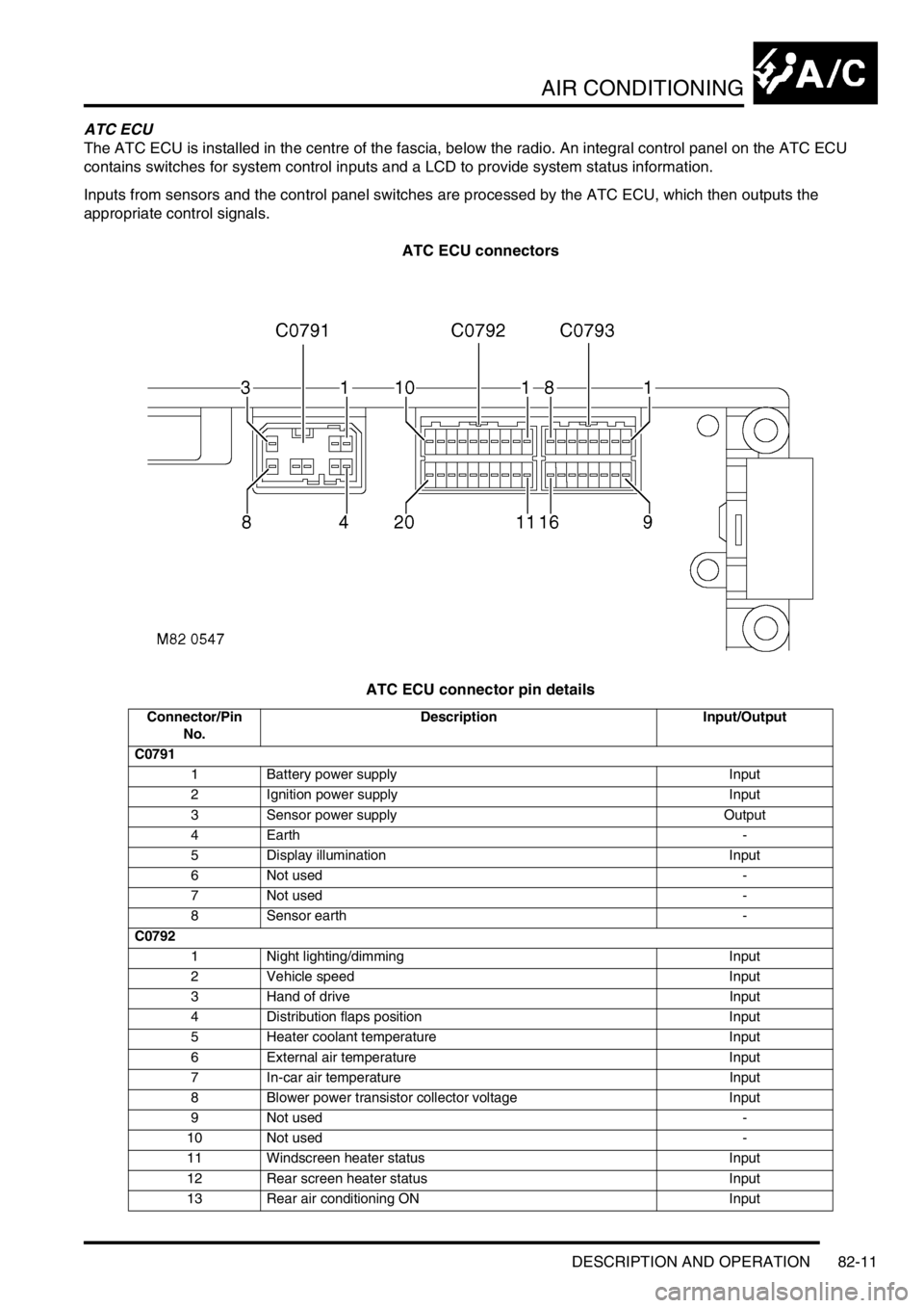
The ATC ECU is installed in the centre of the fascia, below the radio. An integral control panel on the ATC ECU
contains switches for system control inputs and a LCD to provide system status information.
Inputs from sensors and the control panel switches are processed by the ATC ECU, which then outputs the
appropriate control signals.
ATC ECU connectors
ATC ECU connector pin details
Connector/Pin
No.Description Input/Output
C0791
1 Battery power supply Input
2 Ignition power supply Input
3 Sensor power supply Output
4Earth -
5 Display illumination Input
6 Not used -
7 Not used -
8 Sensor earth -
C0792
1 Night lighting/dimming Input
2 Vehicle speed Input
3 Hand of drive Input
4 Distribution flaps position Input
5 Heater coolant temperature Input
6 External air temperature Input
7 In-car air temperature Input
8 Blower power transistor collector voltage Input
9 Not used -
10 Not used -
11 Windscreen heater status Input
12 Rear screen heater status Input
13 Rear air conditioning ON Input
Page 1202 of 1529

AIR CONDITIONING
DESCRIPTION AND OPERATION 82-13
The control panel switches are all non-latching pushswitches except for the LH and RH temperature switches, which
are centre-off rocker switches. The switches have the following functions:
LH and RH temperature switches. Enabled only while the system is on:
lEach press increases or decreases the related temperature setting, in steps of 1 °C (2 °F), between 16 and 28
°C (60 and 84 °F).
lIf the decrease side of the switch is pressed when a temperature of 16 °C (60 °F) is set, the display changes to
LO (maximum cold).
lIf the increase side of the switch is pressed when a temperature of 28 °C (84 °F) is set, the display changes to
HI (maximum hot).
lIf a switch is kept depressed, step changes occur every 0.4 seconds.
A/C on/off switch. Switches the system on and off. When used to switch the system on, the system resumes the
configuration in use prior to the previous off selection.
Blower switch. Enabled only while the system is on. Provides manual control of blower speed:
lEach press changes the blower speed, in sequence, through off (only available if economy mode is selected on)
and five incremental speeds.
lIf the switch is kept depressed, after 1 second subsequent speed increments occur every 0.4 second until blower
reaches high speed. Releasing and then pressing the switch again changes blower back to off or low speed.
Distribution switch. Enabled only while the system is on. Provides manual control of air distribution:
lEach press changes the air distribution, in sequence, through footwells only, footwells and windscreen/side
windows demist, windscreen/side windows demist only, face level only, face level and footwells.
lIf the switch is kept depressed, after 1 second subsequent distribution changes occur every 0.4 seconds until
distribution reaches face level and footwells. Releasing and then pressing the switch again changes distribution
back to footwells only.
External air temperature (EXT) switch. Enabled while the system is on or off. Switches the external temperature output
on and off:
lIf the system is already on, the temperature output overrides the system outputs for approximately 7 seconds,
then the display reverts to system outputs.
lIf the system is switched on while the external temperature output is on, the system outputs override the external
temperature output.
Fresh/Recirculated air switch. Enabled only while the system is on. Provides manual control of inlet air selection.
Defrost mode switch. Starts the system in, or switches the system to and from, defrost mode.
Automatic mode (AUTO) switch. Starts the system in, or switches the system to and from, the automatic mode.
Economy mode (ECON) switch. Enabled only while the system is on. Provides manual on/off control of the refrigerant
system compressor, to reduce fuel consumption when there is no requirement for cool or dehumidified air, e.g. when
the ambient temperature is lower than the LH and RH temperature settings.
Temperature settings: The LH and RH temperature settings are reference inputs used by the control system and give
an approximation of the temperatures that will be established in the cabin. They are not necessarily actual distribution
outlet temperatures, or the temperatures at specific points in the cabin.
Audible warning: A 'beep' is emitted from the ATC ECU each time it receives a control switch input. This audible
warning can be switched off and on by pressing and holding the AUTO switch, then pressing and holding the A/C on/
off switch until the audible warning sounds (approximately 3 seconds). While switched off, the audible warning still
sounds when:
lSwitching between °F and °C on the display.
lSwitching the audible warning from off to on.
lSwitching the timed feet function on and off.
lSwitching the timed recirculated inlet air on and off.
lSwitching the latched recirculated inlet air on and off.
lWhen there is a fault warning.
lRunning the self diagnostic routine.