1999 LAND ROVER DISCOVERY oil pressure
[x] Cancel search: oil pressurePage 1216 of 1529
AIR CONDITIONING
REFRIGERANT RECOVERY, RECYCLING AND RECHARGING 82-27
REFRIGERANT RECOVERY, RECYCLING AND RECHARGING
Refrigerant recovery, recycling and
recharging
$% 82.30.02
Recovery
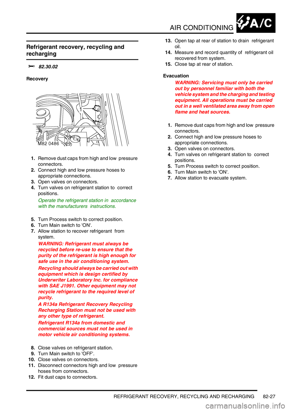
1.Remove dust caps from high and low pressure
connectors.
2.Connect high and low pressure hoses to
appropriate connections.
3.Open valves on connectors.
4.Turn valves on refrigerant station to correct
positions.
Operate the refrigerant station in accordance
with the manufacturers instructions.
5.Turn Process switch to correct position.
6.Turn Main switch to 'ON'.
7.Allow station to recover refrigerant from
system.
WARNING: Refrigerant must always be
recycled before re-use to ensure that the
purity of the refrigerant is high enough for
safe use in the air conditioning system.
Recycling should always be carried out with
equipment which is design certified by
Underwriter Laboratory Inc. for compliance
with SAE J1991. Other equipment may not
recycle refrigerant to the required level of
purity.
A R134a Refrigerant Recovery Recycling
Recharging Station must not be used with
any other type of refrigerant.
Refrigerant R134a from domestic and
commercial sources must not be used in
motor vehicle air conditioning systems.
8.Close valves on refrigerant station.
9.Turn Main switch to 'OFF'.
10.Close valves on connectors.
11.Disconnect connectors high and low pressure
hoses from connectors.
12.Fit dust caps to connectors. 13.Open tap at rear of station to drain refrigerant
oil.
14.Measure and record quantity of refrigerant oil
recovered from system.
15.Close tap at rear of station.
Evacuation
WARNING: Servicing must only be carried
out by personnel familiar with both the
vehicle system and the charging and testing
equipment. All operations must be carried
out in a well ventilated area away from open
flame and heat sources.
1.Remove dust caps from high and low pressure
connectors.
2.Connect high and low pressure hoses to
appropriate connections.
3.Open valves on connectors.
4.Turn valves on refrigerant station to correct
positions.
5.Turn Process switch to correct position.
6.Turn Main switch to 'ON'.
7.Allow station to evacuate system.
Page 1217 of 1529

AIR CONDITIONING
82-28REFRIGERANT RECOVERY, RECYCLING AND RECHARGING
Recharging
NOTE: When recharging, always make
allowance for refrigerant in the line between the
charging station and the vehicle. This is
calculated at 30 grammes/metre of charging
line. System charge weights are 700
± 25
grammes for front A/C system only and 900
±
25 grammes for combined front and rear A/C
system.
1.Close valves on refrigerant station.
2.Close valve on oil charger.
3.Disconnect yellow hose from refrigerant
station.
4.Remove lid from oil charger.
5.Pour same quantity of refrigerant oil into oil
charger as collected during recovery. If the
following components have been renewed, add
the following additional quantity of lubricating
oil:
lCondenser = 40 cm
3
lEvaporator = 40 cm3
lPipe or hose = 5 cm3/metre
lReceiver/dryer = 15 cm3.
6.Fit lid to oil charger.
7.Connect yellow hose to refrigerant station.
8.Open valve on oil charger.
9.Move pointer on refrigerant gauge to mark
position of refrigerant charge quantity.
+ CAPACITIES, FLUIDS,
LUBRICANTS AND SEALANTS, Capacities.
10.Slowly open correct valve on refrigerant station
and allow vacuum to pull refrigerant into
system.
11.Close valve on refrigerant station when correct
amount of refrigerant has been drawn into air
conditioning system.
12.Turn Main switch to 'OFF'.
13.Close valves on connectors.
14.Disconnect high and low pressure hoses from
connectors.
15.Fit dust caps to connectors.
Page 1222 of 1529
AIR CONDITIONING
REPAIRS 82-33
Refit
1.Fit captive nut plates to new condenser.
2.Fit seal to condenser.
3.Fit RH mounting bracket to condenser and
secure with bolt.
4.Fit receiver drier bracket assembly and secure
with bolts.
5.Ensure condenser pipe and new receiver drier
connections are clean.
6.Lubricate new 'O' ring with refrigerant oil and fit
to condenser pipe.
7.Fit receiver drier to bracket and condenser
pipe. Tighten bolt securing condenser pipe to 5
Nm (3.7 lbf.ft). Fit clamping bolt securing
receiver drier to bracket and tighten to 5 Nm
(3.7 lbf.ft).
8.Ensure adaptor block and receiver drier
connections are clean.
9.Lubricate new 'O' ring with refrigerant oil and fit
to adaptor block.
10.Fit adaptor block to receiver drier and tighten
bolt to 5 Nm. (3.7 lbf.ft).
11.Fit condenser assembly.
12.Fit cooling fan to condenser and fit bolts to
secure support rails to condenser brackets.
13.Ensure connections of condenser, receiver
drier and evaporator pipes are clean.
14.Lubricate new 'O' ring seals with refrigerant oil
and fit one seal to each evaporator pipe.
15.Connect evaporator pipes and tighten bolts to 5
Nm (3.7 lbf.ft).
16.Connect multiplug to dual pressure switch.
17.Fit radiator.
l
+ COOLING SYSTEM - Td5,
REPAIRS, Radiator.
l
+ COOLING SYSTEM - V8,
REPAIRS, Radiator.
18.Recharge A/C system.
+ AIR CONDITIONING, REFRIGERANT
RECOVERY, RECYCLING AND
RECHARGING, Refrigerant recovery,
recycling and recharging.
Receiver drier and dual pressure switch
$% 82.17.03
Remove
1.Recover refrigerant from air conditioning
system.
+ AIR CONDITIONING, REFRIGERANT
RECOVERY, RECYCLING AND
RECHARGING, Refrigerant recovery,
recycling and recharging.
2.Remove front grille.
+ EXTERIOR FITTINGS, REPAIRS,
Grille - front - up to 03MY.
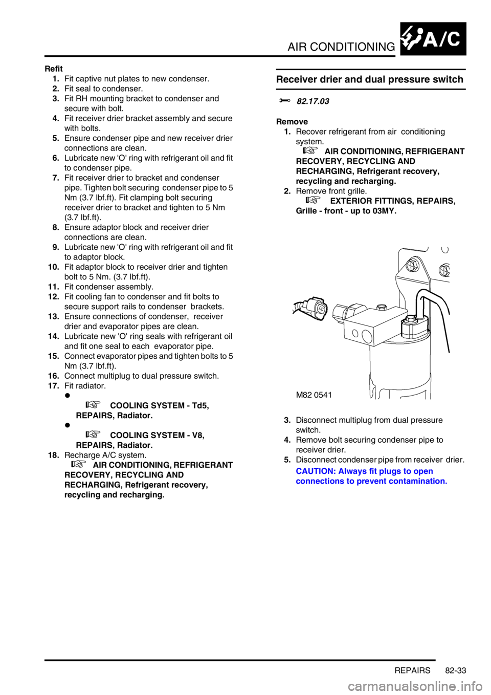
3.Disconnect multiplug from dual pressure
switch.
4.Remove bolt securing condenser pipe to
receiver drier.
5.Disconnect condenser pipe from receiver drier.
CAUTION: Always fit plugs to open
connections to prevent contamination.
Page 1223 of 1529
AIR CONDITIONING
82-34REPAIRS
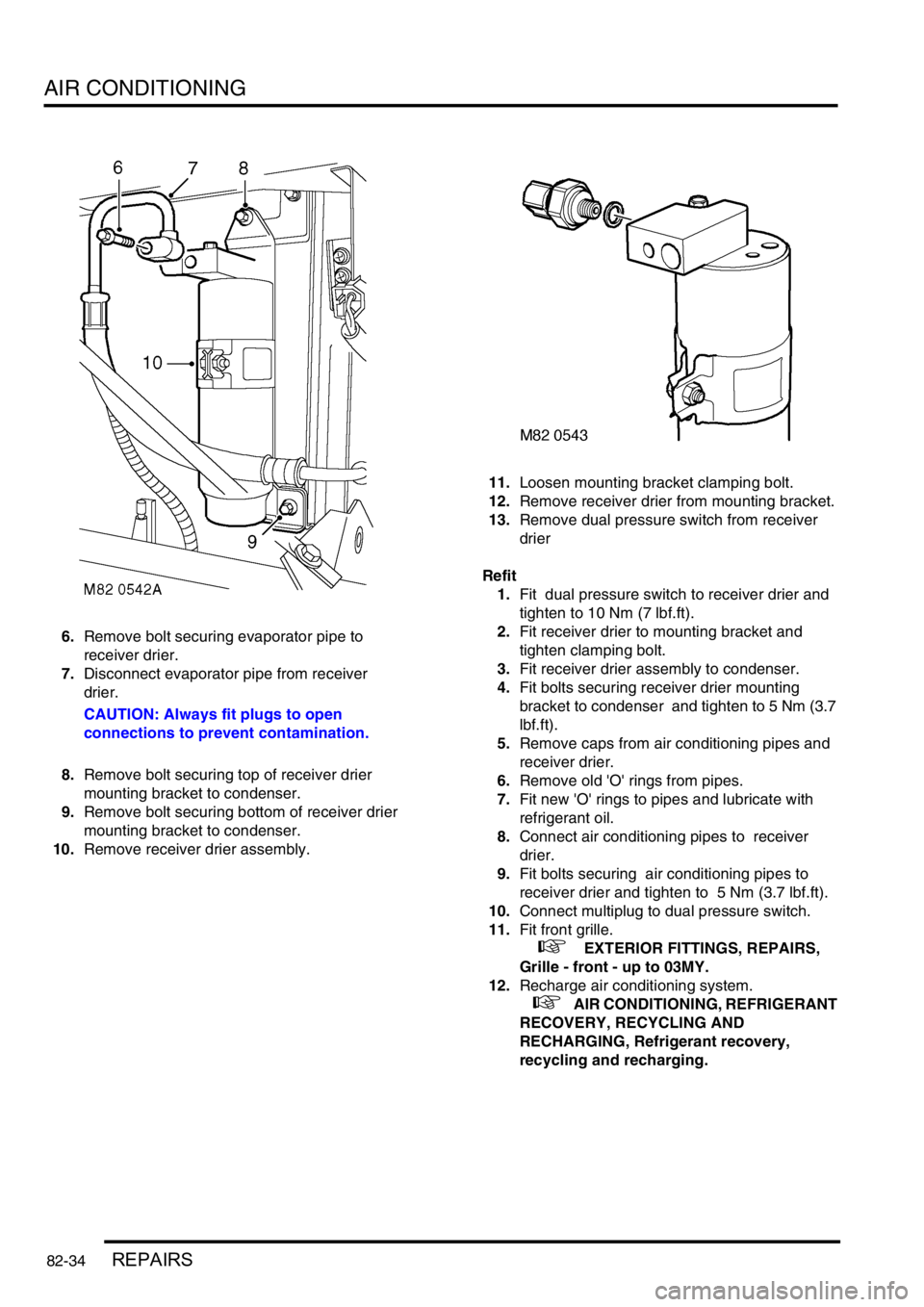
6.Remove bolt securing evaporator pipe to
receiver drier.
7.Disconnect evaporator pipe from receiver
drier.
CAUTION: Always fit plugs to open
connections to prevent contamination.
8.Remove bolt securing top of receiver drier
mounting bracket to condenser.
9.Remove bolt securing bottom of receiver drier
mounting bracket to condenser.
10.Remove receiver drier assembly. 11.Loosen mounting bracket clamping bolt.
12.Remove receiver drier from mounting bracket.
13.Remove dual pressure switch from receiver
drier
Refit
1.Fit dual pressure switch to receiver drier and
tighten to 10 Nm (7 lbf.ft).
2.Fit receiver drier to mounting bracket and
tighten clamping bolt.
3.Fit receiver drier assembly to condenser.
4.Fit bolts securing receiver drier mounting
bracket to condenser and tighten to 5 Nm (3.7
lbf.ft).
5.Remove caps from air conditioning pipes and
receiver drier.
6.Remove old 'O' rings from pipes.
7.Fit new 'O' rings to pipes and lubricate with
refrigerant oil.
8.Connect air conditioning pipes to receiver
drier.
9.Fit bolts securing air conditioning pipes to
receiver drier and tighten to 5 Nm (3.7 lbf.ft).
10.Connect multiplug to dual pressure switch.
11.Fit front grille.
+ EXTERIOR FITTINGS, REPAIRS,
Grille - front - up to 03MY.
12.Recharge air conditioning system.
+ AIR CONDITIONING, REFRIGERANT
RECOVERY, RECYCLING AND
RECHARGING, Refrigerant recovery,
recycling and recharging.
Page 1233 of 1529
AIR CONDITIONING
82-44REPAIRS
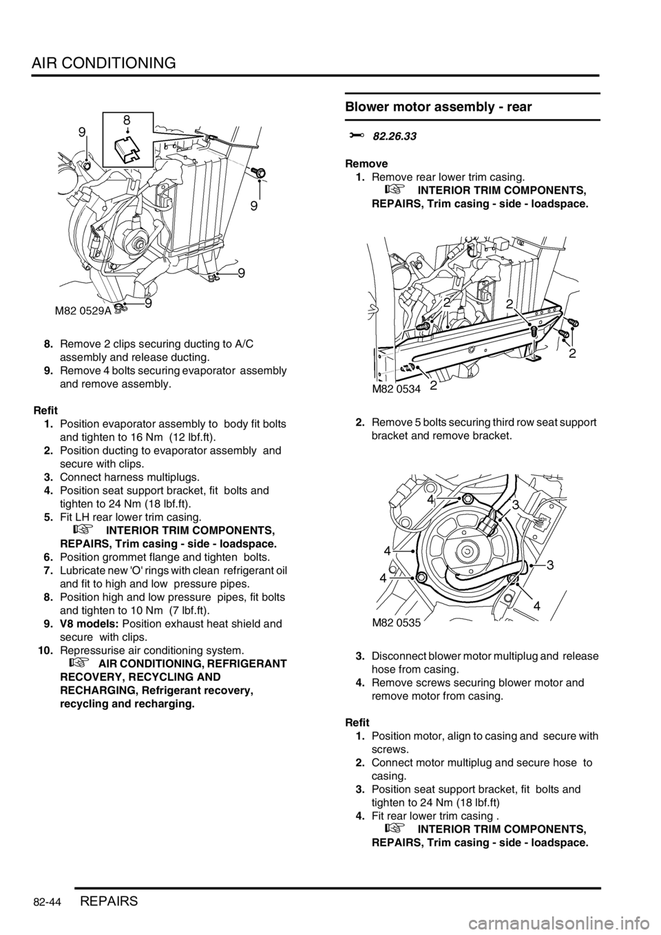
8.Remove 2 clips securing ducting to A/C
assembly and release ducting.
9.Remove 4 bolts securing evaporator assembly
and remove assembly.
Refit
1.Position evaporator assembly to body fit bolts
and tighten to 16 Nm (12 lbf.ft).
2.Position ducting to evaporator assembly and
secure with clips.
3.Connect harness multiplugs.
4.Position seat support bracket, fit bolts and
tighten to 24 Nm (18 lbf.ft).
5.Fit LH rear lower trim casing.
+ INTERIOR TRIM COMPONENTS,
REPAIRS, Trim casing - side - loadspace.
6.Position grommet flange and tighten bolts.
7.Lubricate new 'O' rings with clean refrigerant oil
and fit to high and low pressure pipes.
8.Position high and low pressure pipes, fit bolts
and tighten to 10 Nm (7 lbf.ft).
9. V8 models: Position exhaust heat shield and
secure with clips.
10.Repressurise air conditioning system.
+ AIR CONDITIONING, REFRIGERANT
RECOVERY, RECYCLING AND
RECHARGING, Refrigerant recovery,
recycling and recharging.
Blower motor assembly - rear
$% 82.26.33
Remove
1.Remove rear lower trim casing.
+ INTERIOR TRIM COMPONENTS,
REPAIRS, Trim casing - side - loadspace.
2.Remove 5 bolts securing third row seat support
bracket and remove bracket.
3.Disconnect blower motor multiplug and release
hose from casing.
4.Remove screws securing blower motor and
remove motor from casing.
Refit
1.Position motor, align to casing and secure with
screws.
2.Connect motor multiplug and secure hose to
casing.
3.Position seat support bracket, fit bolts and
tighten to 24 Nm (18 lbf.ft)
4.Fit rear lower trim casing .
+ INTERIOR TRIM COMPONENTS,
REPAIRS, Trim casing - side - loadspace.
Page 1243 of 1529

WIPERS AND WASHERS
84-8 DESCRIPTION AND OPERATION
Description
General
All markets have a common wiper system with headlamp powerwash as an option.
The wipers system comprises two front wipers and one rear wiper which are powered by electric motors. A washer
reservoir is located in the front left hand wheel arch and is fitted with two electric pumps. Each pump supplies washer
fluid to either the front or rear screens. On certain models, a third pump can be fitted to operate a headlamp power
wash function. Operation of the front and rear wipers and washers is controlled by the driver using switches located
on a steering column stalk and push button switches on the fascia.
Control of the wipers and washers is achieved by the following components:
lBCU.
lIDM.
lFront wiper relay.
lFront wash/ wipe switch.
lVariable delay switch.
lFront wiper motor assembly.
lFront washer pump motor.
lRear wiper relay.
lRear wiper switch.
lRear washer switch.
lRear wiper motor.
lRear washer pump motor.
Both the Body Control Unit (BCU) and the Intelligent Driver Module (IDM) control the wiper system. The BCU controls
the time delay function of the wiper system and is located below and behind the passenger glovebox. During engine
cranking the BCU prevents wiper functions. Two relays are located in the passenger compartment fusebox. The
relays control the delay operation of the front and rear wipers. The relays are an integral part of the fusebox and
cannot be renewed separately.
Power for the wiper system is supplied by the IDM, which is integral with the passenger fusebox and cannot be
renewed as a component. A serial communication link allows communication between the IDM and the BCU.
The system has diagnostic capabilities through TestBook.
Front wipers
The two front windscreen wipers are operated by a linkage assembly and an electric motor located under the plenum
grill below the windscreen. The linkage and motor assembly is handed for left and right hand drive vehicles. The motor
is an integral part of the linkage and cannot be replaced separately.
The linkage comprises a pressed steel mounting plate which provides for the attachment of a wheel box at each end.
The mounting plate is secured to the bulkhead with flanged nuts which attach to a stud plate located behind the
bulkhead. A link arm is attached to each wheel box by a short link and secured with circlips. The link arm has an
attachment hole centrally located along its length for the electric motor drive link.
The electric motor is mounted in a recess in the bulkhead below a sealed cover plate. The drive spindle of the motor
protrudes through the cover plate and is fitted with a link. The link is attached to a tapered spline on the motor spindle
and is secured with a lock washer and nut. The opposite end of the link is attached to the central attachment point on
the link arm and secured with a circlip.
Each wheel box has a taper splined shaft which allows for the attachment of the wiper arm which is secured with a
washer and nut. The shaft of each wheel box is passed through a rubber sealed aperture in the plenum. The wiper
arm attachment to the splined shaft has a pivot to which the remainder of the arm is attached. The two parts of the
arm are connected by a spring which controls the pressure of the blade on the screen to a predetermined amount.
The wiper blades are attached to the wiper arms with a clips that allow the blade to pivot. Each wiper blade comprises
a number of levers and yokes to which the rubber wiper is attached. The levers and yokes ensure that the pressure
applied by the arm spring is distributed evenly along the full length of the blade. The rubber wiper is held in the yokes
by a pair of stainless steel strips which also contribute to the even distribution of spring pressure along the blade. The
driver's side wiper blade is fitted with an aerofoil which presses the blade onto the screen at high speed. This prevents
the blade from lifting off the screen and maintains the wiping performance.
Page 1416 of 1529
HARNESSES
REPAIRS 86-7-11
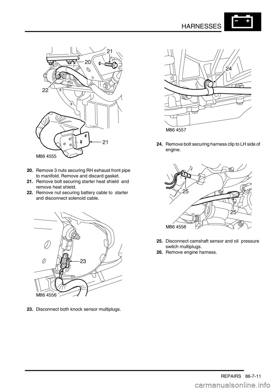
20.Remove 3 nuts securing RH exhaust front pipe
to manifold. Remove and discard gasket.
21.Remove bolt securing starter heat shield and
remove heat shield.
22.Remove nut securing battery cable to starter
and disconnect solenoid cable.
23.Disconnect both knock sensor multiplugs.24.Remove bolt securing harness clip to LH side of
engine.
25.Disconnect camshaft sensor and oil pressure
switch multiplugs.
26.Remove engine harness.
Page 1417 of 1529
HARNESSES
86-7-12 REPAIRS
Refit
1.Position engine harness around engine.
2.Connect oil pressure switch and camshaft
sensor multiplugs.
3.Fit and tighten bolt securing harness to LH side
of engine.
4.Connect both knock sensor multiplugs.
5.Connect battery cable and solenoid cable to
starter motor.
6.Position starter heat shield and secure with
bolt.
7.Clean exhaust flange mating faces, using a
new gasket align exhaust fit nuts and tighten to
60 Nm (44 lbf.ft).
8.Remove stand(s) and lower vehicle.
9.Position harness into footwell and secure
grommet.
10.Connect ECM multiplugs.
11.Position toe board and secure with trim fixings.
12.Connect engine harness to main harness
multiplug and secure earth lead.
13.Connect EVAP solenoid multiplug.
14.Connect both fuse box multiplugs.
15.Position starter lead to fuse box and secure
screw.
16.Fit fuse box cover.
17.Position battery positive lead to battery and
secure nut.
18.Secure harness to coolant rail.
19.Position alternator cables and tighten terminal
B+ to 18 Nm (13 lbf.ft) and terminal D+ to 5 Nm
(3.7 lbf.ft)
20.Connect coolant temperature sensor multiplug.
21.Connect A/C compressor multiplug.
22.Secure harness clip to rear of LH cylinder head.
23.Connect CKP sensor multiplug.
24.Secure injector harness and connect injector
multiplugs.
25.Connect coil multiplugs.
26.Connect and secure HS
2O sensor multiplug
27.Fit upper inlet manifold.
+ MANIFOLDS AND EXHAUST
SYSTEMS - V8, REPAIRS, Gasket - inlet
manifold - upper - Without Secondary Air
Injection.
28.Connect battery earth lead.
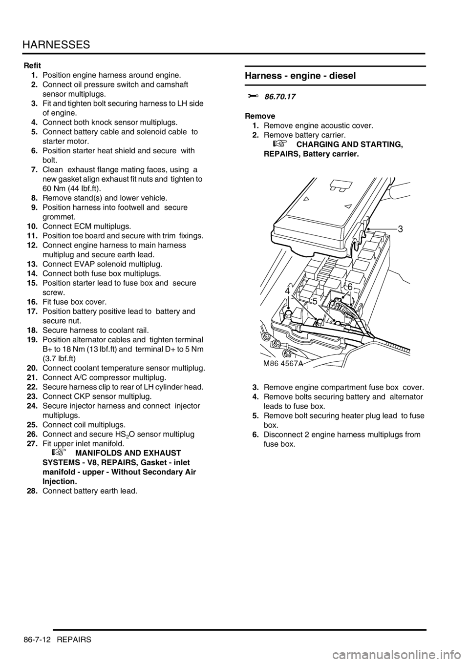
Harness - engine - diesel
$% 86.70.17
Remove
1.Remove engine acoustic cover.
2.Remove battery carrier.
+ CHARGING AND STARTING,
REPAIRS, Battery carrier.
3.Remove engine compartment fuse box cover.
4.Remove bolts securing battery and alternator
leads to fuse box.
5.Remove bolt securing heater plug lead to fuse
box.
6.Disconnect 2 engine harness multiplugs from
fuse box.