1999 LAND ROVER DISCOVERY height
[x] Cancel search: heightPage 1056 of 1529

CHASSIS AND BODY DIMENSIONS
BODY DIMENSIONS 77-1-5
BODY DIMENSIONS
Body Dimensions
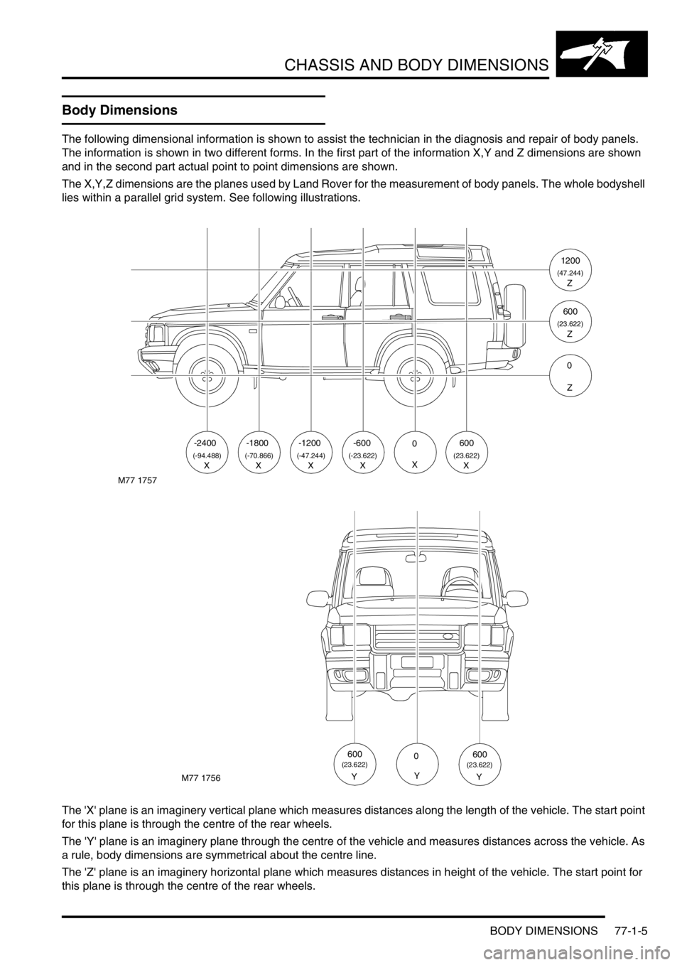
The following dimensional information is shown to assist the technician in the diagnosis and repair of body panels.
The information is shown in two different forms. In the first part of the information X,Y and Z dimensions are shown
and in the second part actual point to point dimensions are shown.
The X,Y,Z dimensions are the planes used by Land Rover for the measurement of body panels. The whole bodyshell
lies within a parallel grid system. See following illustrations.
The 'X' plane is an imaginery vertical plane which measures distances along the length of the vehicle. The start point
for this plane is through the centre of the rear wheels.
The 'Y' plane is an imaginery plane through the centre of the vehicle and measures distances across the vehicle. As
a rule, body dimensions are symmetrical about the centre line.
The 'Z' plane is an imaginery horizontal plane which measures distances in height of the vehicle. The start point for
this plane is through the centre of the rear wheels.
M77 1757
-2400
(-94.488)X
-1800
(-70.866)
-1200-6000600
(-47.244)(-23.622)(23.622)XXXXX
1200
(47.244)Z
600
(23.622)Z
0
Z
M77 1756
0
Y
600(23.622)
Y
600(23.622)
Y
Page 1274 of 1529

LIGHTING
ADJUSTMENTS 86-2-1
LIGHTING ADJUST ME NTS
Headlamps beam alignment - up to 03MY
$% 86.40.17
Check
1.Ensure vehicle is unladen and tyres are at
correct pressures.
2. Models with SLS: Ensure vehicle is at
standard ride height.
3. Models with headlamp levelling: Ensure
headlamp levelling switch is set to '0'.
4.Align suitable beam setting equipment to
headlamp.
5.Switch headlamps on and measure main beam
settings. Beam must be 1.4% below the
horizontal and parallel to the vehicle centre line.
If necessary, adjust headlamp to get correct
beam settings.
6.Align beam setting equipment to 2nd headlamp
and repeat check.
7.Switch off headlamps and remove beam setting
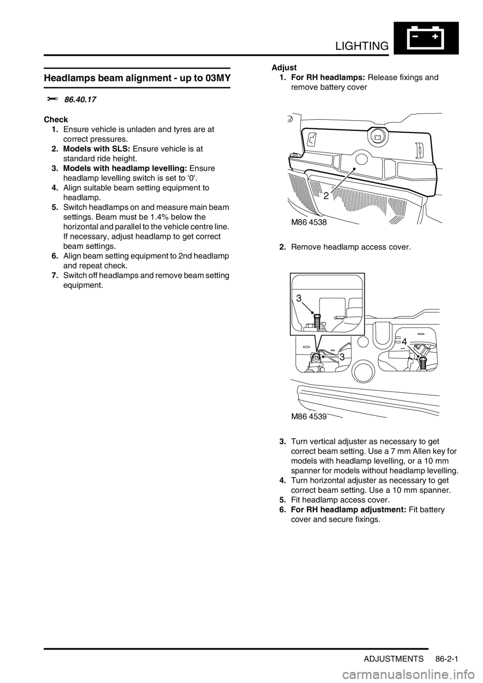
equipment.Adjust
1. For RH headlamps: Release fixings and
remove battery cover
2.Remove headlamp access cover.
3.Turn vertical adjuster as necessary to get
correct beam setting. Use a 7 mm Allen key for
models with headlamp levelling, or a 10 mm
spanner for models without headlamp levelling.
4.Turn horizontal adjuster as necessary to get
correct beam setting. Use a 10 mm spanner.
5.Fit headlamp access cover.
6. For RH headlamp adjustment: Fit battery
cover and secure fixings.
Page 1275 of 1529

LIGHTING
86-2-2 ADJUSTMENTS
Headlamps beam alignment - from 03MY
$% 86.40.17
Check
1.Ensure vehicle is unladen and tyres are set at
the correct pressures.
2. Models with SLS: Ensure vehicle is at the
standard ride height.
3. Models without SLS: Set headlamp leveling
switch to zero.
4.Align beam setting equipment to headlamp.
5.Switch on headlamps. Headlamp setting 1.2%
below horizontal and parallel.
6.Align beam setting equipment to second
headlamp and repeat the check.
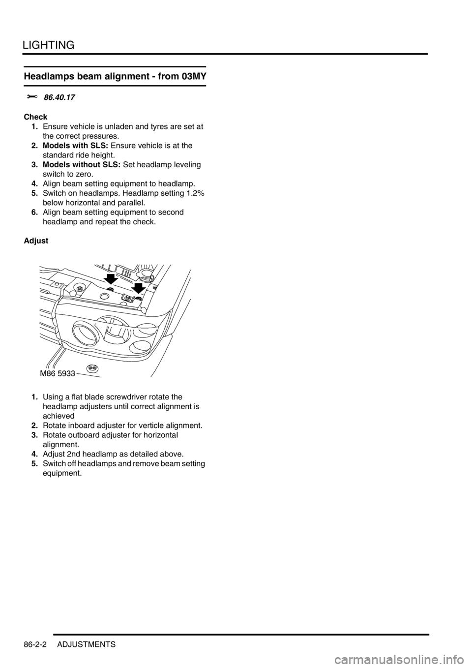
Adjust
1.Using a flat blade screwdriver rotate the
headlamp adjusters until correct alignment is
achieved
2.Rotate inboard adjuster for verticle alignment.
3.Rotate outboard adjuster for horizontal
alignment.
4.Adjust 2nd headlamp as detailed above.
5.Switch off headlamps and remove beam setting
equipment.
Page 1321 of 1529

BODY CONTROL UNIT
86-3-34 DESCRIPTION AND OPERATION
Key-in warning
The BCU can be programmed to one of two options:
lOption 1 – no timeout.
lOption 2 – no key-in warning.
The BCU issues an audible warning No. 2 request, depending on the status of the following inputs:
lIgnition state.
lIgnition key inserted.
lDriver's door open.
If the key-in warning is programmed into the BCU for operation, audible warning No.2 will be requested if the ignition
switch is off, the ignition key inserted signal is on and the driver's door open signal is ON.
In the event of a communications link failure occurring, the audible warning request is not sent to the instrument pack.
SLABS HDC warning
The BCU issues an audible warning No. 3 request, depending on the status of the following inputs:
lIgnition state.
lSLABS HDC warning.
The SLABS warning transmitted by the SLABS ECU is a 2 Hz signal, audible warning No. 3 is requested on every
falling edge of this signal. If the signal from the SLABS ECU stays low for more than 650 ms, audible warning No. 3
is requested every 2 seconds, for 30 seconds, while the signal stays low.
In the event of a communications link failure occurring, the audible warning request is not sent to the instrument pack.
Transfer box in neutral warning
If the transfer box is in the neutral position and the ignition switch is on, the BCU issues an audible warning No. 4
request. The BCU checks for the following inputs:
lTransfer box neutral selected.
lIgnition on.
The transfer box in neutral warning is activated by communicating with the instrument pack via the serial datalink. If
a communications link failure occurs while the transfer box in neutral warning is active, the audible warning will not
operate.
Lights on warning
If the ignition switch is off while the side lamps or headlamps on and the driver's door is opened, the BCU issues an
audible warning No. 5 request.
The BCU checks for the following inputs:
lDriver's door open.
lIgnition on.
lSide lamps.
lDipped beam state.
lMain beam state.
The lights on warning is activated by communicating with the instrument pack via the serial datalink. If a
communications link failure occurs while the lights on warning is active, the audible warning will not operate.
SLABS raise/lower
Before enabling a SLS vehicle raise/ lower request, the BCU checks the logical condition of the following inputs:
lIgnition state.
lSLABS raise request.
lSLABS lower request.
If the ignition switch is in position 0 or I, the vehicle raise/ lower request is off.
With the ignition switch in position II, and the 'SLABS raise' request and 'SLABS lower' request both off, the vehicle
raise/ lower request output is driven at 25 Hz with a 50% duty cycle and the vehicle height remains unchanged.
If the 'SLABS lower' request input is on, the vehicle raise/lower request output is driven at 25 Hz with a 25% duty cycle,
lowering the vehicle.
If the 'SLABS raise' request input is on, the vehicle raise/lower request output is driven at a 25 Hz with a 75% duty
cycle.
Page 1509 of 1529

INSTRUMENTS
88-26 DESCRIPTION AND OPERATION
Off road mode warning lamp
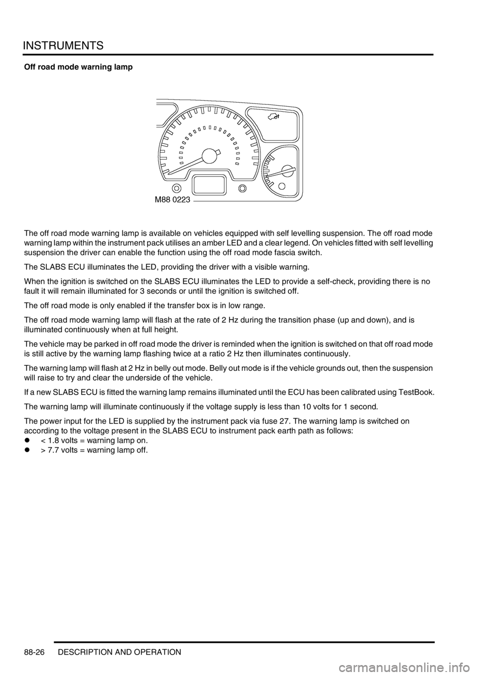
The off road mode warning lamp is available on vehicles equipped with self levelling suspension. The off road mode
warning lamp within the instrument pack utilises an amber LED and a clear legend. On vehicles fitted with self levelling
suspension the driver can enable the function using the off road mode fascia switch.
The SLABS ECU illuminates the LED, providing the driver with a visible warning.
When the ignition is switched on the SLABS ECU illuminates the LED to provide a self-check, providing there is no
fault it will remain illuminated for 3 seconds or until the ignition is switched off.
The off road mode is only enabled if the transfer box is in low range.
The off road mode warning lamp will flash at the rate of 2 Hz during the transition phase (up and down), and is
illuminated continuously when at full height.
The vehicle may be parked in off road mode the driver is reminded when the ignition is switched on that off road mode
is still active by the warning lamp flashing twice at a ratio 2 Hz then illuminates continuously.
The warning lamp will flash at 2 Hz in belly out mode. Belly out mode is if the vehicle grounds out, then the suspension
will raise to try and clear the underside of the vehicle.
If a new SLABS ECU is fitted the warning lamp remains illuminated until the ECU has been calibrated using TestBook.
The warning lamp will illuminate continuously if the voltage supply is less than 10 volts for 1 second.
The power input for the LED is supplied by the instrument pack via fuse 27. The warning lamp is switched on
according to the voltage present in the SLABS ECU to instrument pack earth path as follows:
l< 1.8 volts = warning lamp on.
l> 7.7 volts = warning lamp off.
Page 1519 of 1529

INSTRUMENTS
88-36 DESCRIPTION AND OPERATION
Self Levelling Suspension (SLS) warning lamp
The SLS warning lamp within the instrument pack utilises an amber LED and a clear legend. The SLABS ECU
illuminates the LED continuously if a fault within the SLS is detected, providing the driver with a visible warning.
When the ignition is switched on the SLABS ECU illuminates the LED to provide a self-check, providing there is no
fault it will remain illuminated for 3 seconds or until the ignition is switched off.
On vehicles equipped with coil springs the SLS warning lamp is extinguished after 850 milliseconds if the SLABS ECU
configuration of the vehicle is correct.
The SLS warning lamp flashes at 2 Hz when the remote handset control is used to raise or lower the ride height.
If a new SLABS ECU is installed the SLS warning lamp will remain illuminated until the ECU has been calibrated by
TestBook.
The warning lamp will illuminate continuously when battery voltage is less than 10 volts for greater than 1 second.
When the vehicle is in transportation mode the SLS warning lamp is illuminated continuously with ignition on, and will
flash at 2 Hz frequency as the vehicle rises from bump stop level to transport level on engine start.
The power input for the LED is supplied by the instrument pack via fuse 27. The SLABS ECU provides the earth path
to illuminate the warning lamp.
The voltage on the earth path from the SLABS ECU to the instrument pack has the following functions:
l< 1.8 volts = warning lamp on.
l> 7.7 volts = warning lamp off.