Page 1448 of 1529

DRIVING AIDS
DESCRIPTION AND OPERATION 86-8-11
Operation
PDC System Operation
When the ignition switch is in position II and reverse gear is selected, the PDC sensors are automatically activated.
The PDC ECU only activates the system if reverse is selected for more than 1 second. This avoids nuisance audible
warnings when the gear selector lever is being moved between Drive and Park on vehicles with automatic
transmission.
When the system is activated, the PDC ECU illuminates the indicator LED in the PDC switch, switches on the
ultrasonic sensors and generates a single chime on the PDC sounder to indicate the system is active. If an object is
range of the sensors when the system is activated, a series of audible warnings are emitted by the PDC sounder
immediately.
If PDC operation is not required, it can be suspended temporarily by pressing the PDC switch. When reverse is
deselected and subsequently reselected, PDC will automatically become active again.
PDC can also be manually selected when not in reverse gear by pressing the PDC switch. A second press of the
switch is required to turn off the PDC or the PDC will be deactivated if reverse is selected and then deselected.
Sensor Operation
The PDC ECU processes the distance readings from the ultrasonic sensors to determine if there are any objects
within the detection areas. If there are no objects in the detection areas, there are no further audible warnings. If an
object is detected, repeated audible warnings are produced on the PDC sounder.
The maximum detection range is 1800 mm (70 in). When an object is detected, the time delay between the audible
warning tones decreases as the distance between the detected object and the vehicle decreases until, at
approximately 450 mm (17 in), the audible warning tone is continuous.
After the initial detection of an object, if there is no decrease in the distance between an object and the central sensors,
the time delay between the audible warnings remains constant. If an object is detected by one of the corner sensors
only, the audible warnings stop after about 5 seconds if there is no change in the distance between the object and the
corner sensor.
Page 1489 of 1529

INSTRUMENTS
88-6 DESCRIPTION AND OPERATION
The third warning lamp pack is located in the top right-hand side of the instrument pack and contains the following
warning lamps:
lSRS warning lamp.
lSLS off road mode warning lamp.
lTrailer warning lamp.
lGlow plug warning lamp.
lWater in fuel filter warning lamp.
lSeat belt warning lamp.
lTransmission high temperature warning lamp.
The fourth warning lamp pack is located underneath the tachometer of the instrument pack contains the following
warning lamps:
lOil pressure warning lamp.
lAlternator charge warning lamp.
lHDC fault warning lamp.
lSelf Levelling Suspension (SLS) warning lamp.
lActive Cornering Enhancement (ACE) warning lamp.
lGearbox manual/sport mode warning lamps.
The serial communication link is used to allow information to travel to and from the instrument pack, and it provides
the ability to configure the instrument pack to a specific market. It also allows the instrument pack to be controlled by
TestBook for diagnostics.
There are five market specific variants of the instrument pack:
lUnited Kingdom (UK).
lNorth American Specification (NAS).
lCanada.
lAustralia.
lRest Of the World (ROW), Gulf and Japan.
The main difference between the five markets is that the speedometer will indicate road speed in mph as major figures
and km/h as minor figures, km/h as major figures and mph as minor figures or km/h only.
When TestBook is used to diagnose the instrument pack it demands each of the dials and warning lamps to operate
in-turn so a visual check of their operation can be made.
CAUTION: The instrument pack must not be stored on its face side at any time. This is because the dials have
damping fluid within them to ensure smooth operation of the dials' indicator needles. This fluid will leak out.
Speedometer
The speedometer informs the driver of the current vehicle road speed. It has a Liquid Crystal Display (LCD) to show
odometer, trip meter and, on automatic gearbox models, the selected gear. The speedometer will not show speeds
of less than 1.5 mph (2.5 km/h).
There are three different market configurations:
lNAS and UK = mph as major figures km/h as minor figures.
lCanada = km/h as major figures mph as minor figures.
lROW and Australia = km/h only.
The Self Levelling and Anti-Lock Brake System (SLABS) ECU provides the signal input for the road speed. The signal
is at 8000 pulses per mile (1.6 kilometres).
Page 1515 of 1529

INSTRUMENTS
88-32 DESCRIPTION AND OPERATION
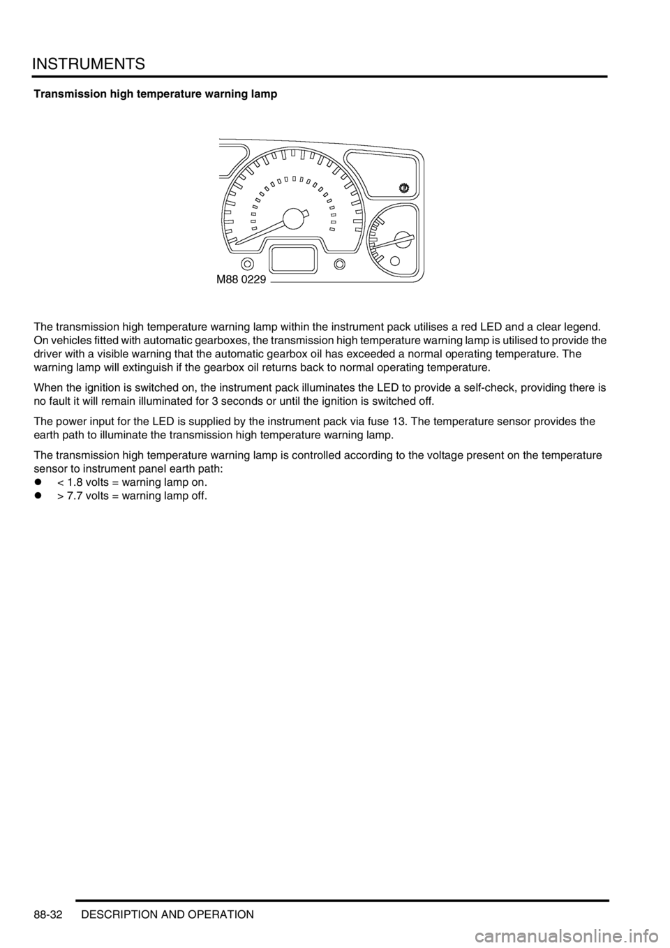
Transmission high temperature warning lamp
The transmission high temperature warning lamp within the instrument pack utilises a red LED and a clear legend.
On vehicles fitted with automatic gearboxes, the transmission high temperature warning lamp is utilised to provide the
driver with a visible warning that the automatic gearbox oil has exceeded a normal operating temperature. The
warning lamp will extinguish if the gearbox oil returns back to normal operating temperature.
When the ignition is switched on, the instrument pack illuminates the LED to provide a self-check, providing there is
no fault it will remain illuminated for 3 seconds or until the ignition is switched off.
The power input for the LED is supplied by the instrument pack via fuse 13. The temperature sensor provides the
earth path to illuminate the transmission high temperature warning lamp.
The transmission high temperature warning lamp is controlled according to the voltage present on the temperature
sensor to instrument panel earth path:
l< 1.8 volts = warning lamp on.
l> 7.7 volts = warning lamp off.
Page 1521 of 1529

INSTRUMENTS
88-38 DESCRIPTION AND OPERATION
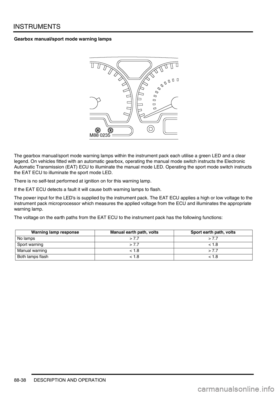
Gearbox manual/sport mode warning lamps
The gearbox manual/sport mode warning lamps within the instrument pack each utilise a green LED and a clear
legend. On vehicles fitted with an automatic gearbox, operating the manual mode switch instructs the Electronic
Automatic Transmission (EAT) ECU to illuminate the manual mode LED. Operating the sport mode switch instructs
the EAT ECU to illuminate the sport mode LED.
There is no self-test performed at ignition on for this warning lamp.
If the EAT ECU detects a fault it will cause both warning lamps to flash.
The power input for the LED's is supplied by the instrument pack. The EAT ECU applies a high or low voltage to the
instrument pack microprocessor which measures the applied voltage from the ECU and illuminates the appropriate
warning lamp.
The voltage on the earth paths from the EAT ECU to the instrument pack has the following functions:
Warning lamp response Manual earth path, volts Sport earth path, volts
No lamps > 7.7 > 7.7
Sport warning > 7.7 < 1.8
Manual warning < 1.8 > 7.7
Both lamps flash < 1.8 < 1.8
Page 1525 of 1529

INSTRUMENTS
88-42 DESCRIPTION AND OPERATION
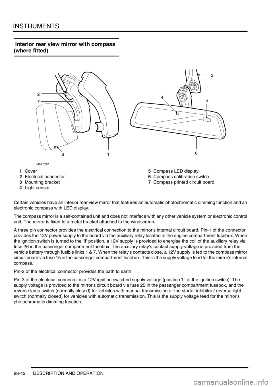
Interior rear view mirror with compass
(where fitted)
1Cover
2Electrical connector
3Mounting bracket
4Light sensor5Compass LED display
6Compass calibration switch
7Compass printed circuit board
Certain vehicles have an interior rear view mirror that features an automatic photochromatic dimming function and an
electronic compass with LED display.
The compass mirror is a self-contained unit and does not interface with any other vehicle system or electronic control
unit. The mirror is fixed to a metal bracket attached to the windscreen.
A three pin connector provides the electrical connection to the mirror's internal circuit board. Pin-1 of the connector
provides the 12V power supply to the board via the auxiliary relay located in the engine compartment fusebox. When
the ignition switch is turned to the 'II' position, a 12V supply is provided to energise the coil of the auxiliary relay via
fuse 26 in the passenger compartment fusebox. The auxiliary relay's contact supply voltage is provided from the
vehicle battery through fusible links 1 & 7. When the relay's contacts close, a 12V supply is fed to the compass mirror
circuit board via fuse 15 in the passenger compartment fusebox. This is the supply voltage feed for the mirror's internal
compass.
Pin-2 of the electrical connector provides the path to earth.
Pin-3 of the electrical connector is a 12V ignition switched supply voltage (position 'II' of the ignition switch). The
supply voltage is provided to the mirror's circuit board via fuse 25 in the passenger compartment fusebox, and the
reverse lamp switch (normally closed) for vehicles with manual transmission or the starter inhibitor / reverse light
switch (normally closed) for vehicles with automatic transmission. This is the supply voltage feed for the mirror's
photochromatic dimming function.
M88 0297
3
2
7
616
45