1999 LAND ROVER DISCOVERY oil temperature
[x] Cancel search: oil temperaturePage 566 of 1529

TRANSFER BOX - LT230SE
REPAIRS 41-41
Sensor - neutral
$% 41.20.64
Remove
1.Raise vehicle on ramp.
2.Disconnect multiplug from neutral sensor.
3.Remove sensor and discard sealing washer.
Refit
1.Clean sensor threads.
2.Fit new washer and apply sealant, Part No.
STC 50552 to threads of sensor.
3.Fit and tighten sensor to 25 Nm (18 lbf.ft).
4.Lower vehicle on ramp.
Sensor - oil temperature - If fitted
$% 41.20.80
Remove
1.Lower vehicle.
2.Disconnect 2 Lucar connectors from oil
temperature sensor.
3.Remove oil temperature sensor and discard
sealing washer.
Refit
1.Clean sensor and mating face on transfer box.
2.Fit new sealing washer, position oil
temperature sensor and tighten to 25 Nm (18
lbf.ft).
3.Connect Lucar connectors to oil temperature
sensor.
4.Lower vehicle.
Page 610 of 1529

AUTOMATIC GEARBOX - ZF4HP22 - 24
DESCRIPTION AND OPERATION 44-13
Oil cooler
1Inlet connection
2Fixing bracket
3Outlet connection4Fixing bracket
5Temperature sensor
Transmission fluid from the gearbox is circulated through a cooler attached to the front of the radiator. Quick release
connectors on the transmission fluid lines attach to connections on each end tank of the cooler. A temperature sensor
on the RH end tank provides the instrument pack with an input of transmission fluid temperature. If the temperature
exceeds a preset limit, the instrument pack illuminates the transmission temperature warning lamp. The warning lamp
remains illuminated until the temperature of the fluid returns within limits.
EAT ECU
The EAT ECU operates the solenoid valves in the gearbox to provide automatic control of gear shifts and torque
converter lock-up. The EAT ECU is attached to a protective bracket which is secured to the cabin floor below the LH
front seat. A 55 pin connector links the EAT ECU to the vehicle wiring.
Software in the EAT ECU monitors hard wired inputs and exchanges information with the ECM on a Controller Area
Network (CAN) bus to determine gear shift and torque converter lock-up requirements. Resultant control signals are
then output to the gearbox solenoid valves.
Page 647 of 1529

AUTOMATIC GEARBOX - ZF4HP22 - 24
44-50 REPAIRS
Cooler - fluid - V8
$% 44.24.10
Remove
1. If fitted: Remove engine oil cooler.
+ ENGINE - V8, REPAIRS, Cooler -
engine oil.
2.Disconnect fluid temperature sensor multiplug.
3.Position absorbent cloth under each gearbox
cooler hose connection to collect spillage.
4.Push against coupling release ring and
disconnect both fluid hoses from cooler.
CAUTION: Always fit plugs to open
connections to prevent contamination.
5.Remove screw and release cooler from
radiator.
6.Carefully move radiator towards engine and
remove cooler.7.Remove temperature sensor and discard
sealing washer.
Refit
1.Use new sealing washer and tighten
temperature sensor to 14 Nm (10 lbf.ft).
2.Fit cooler, engage with radiator and secure with
screw.
3.Connect temperature sensor multiplug.
4.Ensure connections are clean and fit hoses to
cooler.
5. If fitted:Fit engine oil cooler.
+ ENGINE - V8, REPAIRS, Cooler -
engine oil.
6.Check and if necessary top up gearbox fluid.
Page 714 of 1529

STEERING
ADJUSTMENTS 57-21
13.Remove bolt from steering box pipe retaining
clip. Leaving the PAS reservoir oil pipe in place,
release pipe retaining clip and PAS cooler pipe
from steering box, discard the seal.
14.Fit tool LRT-57-041 to steering box housing.
15.Fit seal to PAS oil cooler pipe.
16.Fit PAS cooler pipe to LRT-57-041 align the
retaining clip to pipes and tighten bolt to 24 Nm
(18 lbf.ft).
17.Connect test hoses LRT-57-002 to LRT-57-
041 and tighten unions. Ensure all pipes and
fittings are clear of engine rotating parts.18.Hang pressure gauge in a safe position under
bonnet.
19. LHD only: Fit turbocharger intercooler feed
pipe and vacuum connection and fit PAS
reservoir to mounting bracket. Fit air intake
hose to turbocharger and air cleaner and
connect multiplug to MAF sensor. The above
parts must be refitted in order to run the
engine.
20.Fill PAS reservoir, connect battery earth lead.
Start engine and allow air to bleed from PAS
system, by turning steering from lock to lock.
Stop engine and check PAS fluid level.
21.Ensure steering system is free from leaks and
maintain maximum fluid level during test.
22.Open the test valve on LRT-57-001 and start
the engine.
23.With the engine at idle and normal running
temperature, slowly turn the steering wheel and
hold on lock.
24.Note reading on pressure gauge.
25.Repeat pressure check on opposite lock, again
noting the reading on the pressure gauge.
26.The test pressure should be between 21 and 62
bar, (300 to 900 lbf/in
2. Pressure will rise to 62
bar (900 lbf/in2) when held on full lock.
27.With the engine at idle, centralise the steering
wheel. Pressure should read 7 bar (100 lbf/in
2)
or below.
28.Pressure outside the above tolerance indicates
a fault.
29.To determine if fault is in steering pump or
steering rack, close the valve on LRT-57-001
for a maximum of five seconds. Pump damage
may occur if test valve is closed for longer
periods.
30.If the gauge does not register between 75 and
103 bar, (1500 lbf/in
2) (maximum pump
pressure), the pump is faulty.
31.If maximum pump pressure is obtained,
suspect the steering box.
32.On completion, stop engine, disconnect battery
earth lead and syphon fluid from PAS reservoir.
33. LHD only: Disconnect multiplug from MAF
sensor, remove air intake hose clips and move
hose aside.
34. LHD only: Release PAS reservoir from
mounting, for access to turbocharger
intercooler pipe.Remove vacuum hose from
turbocharger intercooler pipe.Release clips and
disconnect intercooler pipe from turbocharger.
35.Remove test equipment from tool LRT-57-041.
36.Remove bolt and clip from steering box.
37.Release PAS cooler pipe from tool LRT-57-041
and discard seal. leaving PAS reservoir oil pipe
in place, release tool LRT-57-041 from
steering box and discard seal.
Page 1193 of 1529

AIR CONDITIONING
82-4DESCRIPTION AND OPERATION
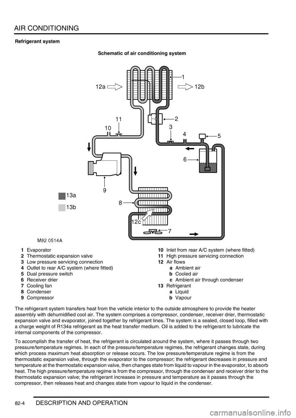
Refrigerant system
Schematic of air conditioning system
1Evaporator
2Thermostatic expansion valve
3Low pressure servicing connection
4Outlet to rear A/C system (where fitted)
5Dual pressure switch
6Receiver drier
7Cooling fan
8Condenser
9Compressor10Inlet from rear A/C system (where fitted)
11High pressure servicing connection
12Air flows
aAmbient air
bCooled air
cAmbient air through condenser
13Refrigerant
aLiquid
bVapour
The refrigerant system transfers heat from the vehicle interior to the outside atmosphere to provide the heater
assembly with dehumidified cool air. The system comprises a compressor, condenser, receiver drier, thermostatic
expansion valve and evaporator, joined together by refrigerant lines. The system is a sealed, closed loop, filled with
a charge weight of R134a refrigerant as the heat transfer medium. Oil is added to the refrigerant to lubricate the
internal components of the compressor.
To accomplish the transfer of heat, the refrigerant is circulated around the system, where it passes through two
pressure/temperature regimes. In each of the pressure/temperature regimes, the refrigerant changes state, during
which process maximum heat absorption or release occurs. The low pressure/temperature regime is from the
thermostatic expansion valve, through the evaporator to the compressor; the refrigerant decreases in pressure and
temperature at the thermostatic expansion valve, then changes state from liquid to vapour in the evaporator, to absorb
heat. The high pressure/temperature regime is from the compressor, through the condenser and receiver drier to the
thermostatic expansion valve; the refrigerant increases in pressure and temperature as it passes through the
compressor, then releases heat and changes state from vapour to liquid in the condenser.
Page 1204 of 1529

AIR CONDITIONING
DESCRIPTION AND OPERATION 82-15
Dual pressure switch
The dual pressure switch protects the refrigerant system from extremes of pressure. The normally closed switch is
installed in the top of the receiver drier. If minimum or maximum pressure limits are exceeded the switch contacts
open, causing the compressor clutch to be disengaged. The minimum pressure limit protects the compressor, by
preventing operation of the system unless there is a minimum refrigerant pressure (and thus refrigerant and
lubricating oil) in the system. The maximum pressure limit keeps the refrigerant system within a safe operating
pressure.
Dual pressure switch nominal operating pressures
Evaporator temperature sensor
The evaporator temperature sensor is an encapsulated thermistor that provides the ATC ECU with an input of the
evaporator air outlet temperature. The evaporator temperature sensor is installed in a clip which locates in the
evaporator matrix in the heater assembly. The ATC ECU uses the input to prevent the formation of ice on the
evaporator.
In-car temperature sensor
The in-car temperature sensor is an encapsulated thermistor that provides the ATC ECU with an input of cabin air
temperature. The sensor is integrated into the inlet of an electric fan, which is installed behind a grille in the fascia
outboard of the steering column. The fan runs continuously, while the ignition is on, to draw air through the grille and
across the sensor.
Sunlight sensor
The sunlight sensor consists of two diodes that provide the ATC ECU with inputs of light intensity, one as sensed
coming from the left of the vehicle and one as sensed coming from the right. The inputs are used as a measure of the
solar heating effect on vehicle occupants. The sensor is installed in the centre of the fascia upper surface.
Heater coolant temperature sensor
The heater coolant temperature sensor is an encapsulated thermistor that provides the ATC ECU with an input related
to heater matrix coolant temperature. The sensor is installed in the casing of the heater assembly and presses against
the end tank of the heater matrix.
Ambient temperature sensor
The ambient temperature sensor is an encapsulated thermistor that provides the ATC ECU with an input of external
air temperature. The sensor is attached to the cooling fan mounting bracket in front of the condenser.
Limit Opening pressure, bar (lbf.in2) Closing pressure, bar (lbf.in2)
Minimum 2.0 (29.0), pressure decreasing 2.3 (33.4), pressure increasing
Maximum 32 (464), pressure increasing 26 (377), pressure decreasing
Page 1417 of 1529

HARNESSES
86-7-12 REPAIRS
Refit
1.Position engine harness around engine.
2.Connect oil pressure switch and camshaft
sensor multiplugs.
3.Fit and tighten bolt securing harness to LH side
of engine.
4.Connect both knock sensor multiplugs.
5.Connect battery cable and solenoid cable to
starter motor.
6.Position starter heat shield and secure with
bolt.
7.Clean exhaust flange mating faces, using a
new gasket align exhaust fit nuts and tighten to
60 Nm (44 lbf.ft).
8.Remove stand(s) and lower vehicle.
9.Position harness into footwell and secure
grommet.
10.Connect ECM multiplugs.
11.Position toe board and secure with trim fixings.
12.Connect engine harness to main harness
multiplug and secure earth lead.
13.Connect EVAP solenoid multiplug.
14.Connect both fuse box multiplugs.
15.Position starter lead to fuse box and secure
screw.
16.Fit fuse box cover.
17.Position battery positive lead to battery and
secure nut.
18.Secure harness to coolant rail.
19.Position alternator cables and tighten terminal
B+ to 18 Nm (13 lbf.ft) and terminal D+ to 5 Nm
(3.7 lbf.ft)
20.Connect coolant temperature sensor multiplug.
21.Connect A/C compressor multiplug.
22.Secure harness clip to rear of LH cylinder head.
23.Connect CKP sensor multiplug.
24.Secure injector harness and connect injector
multiplugs.
25.Connect coil multiplugs.
26.Connect and secure HS
2O sensor multiplug
27.Fit upper inlet manifold.
+ MANIFOLDS AND EXHAUST
SYSTEMS - V8, REPAIRS, Gasket - inlet
manifold - upper - Without Secondary Air
Injection.
28.Connect battery earth lead.
Harness - engine - diesel
$% 86.70.17
Remove
1.Remove engine acoustic cover.
2.Remove battery carrier.
+ CHARGING AND STARTING,
REPAIRS, Battery carrier.
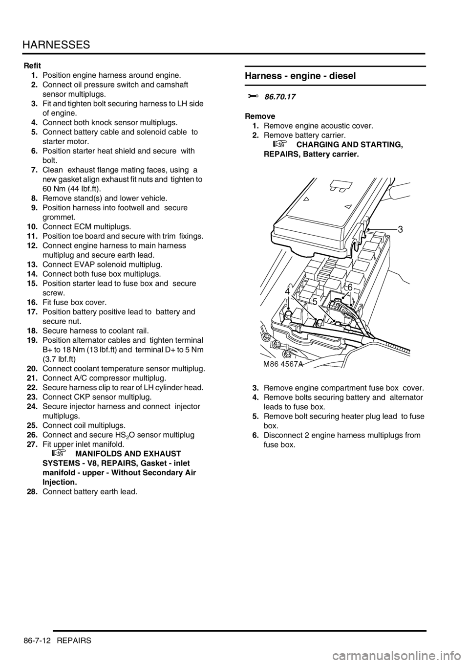
3.Remove engine compartment fuse box cover.
4.Remove bolts securing battery and alternator
leads to fuse box.
5.Remove bolt securing heater plug lead to fuse
box.
6.Disconnect 2 engine harness multiplugs from
fuse box.
Page 1420 of 1529

HARNESSES
REPAIRS 86-7-15
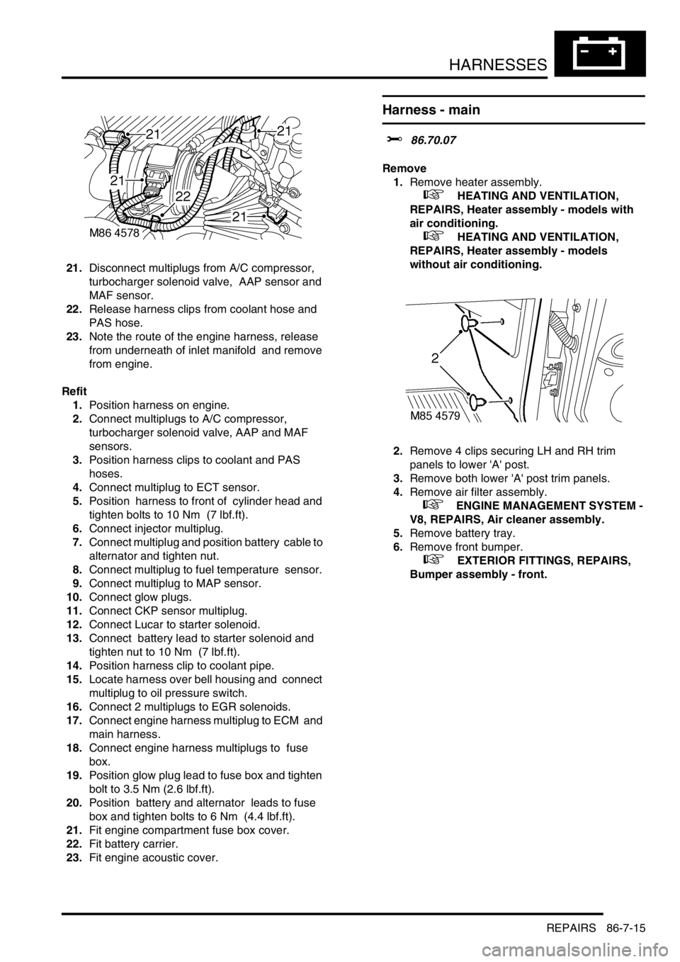
21.Disconnect multiplugs from A/C compressor,
turbocharger solenoid valve, AAP sensor and
MAF sensor.
22.Release harness clips from coolant hose and
PAS hose.
23.Note the route of the engine harness, release
from underneath of inlet manifold and remove
from engine.
Refit
1.Position harness on engine.
2.Connect multiplugs to A/C compressor,
turbocharger solenoid valve, AAP and MAF
sensors.
3.Position harness clips to coolant and PAS
hoses.
4.Connect multiplug to ECT sensor.
5.Position harness to front of cylinder head and
tighten bolts to 10 Nm (7 lbf.ft).
6.Connect injector multiplug.
7.Connect multiplug and position battery cable to
alternator and tighten nut.
8.Connect multiplug to fuel temperature sensor.
9.Connect multiplug to MAP sensor.
10.Connect glow plugs.
11.Connect CKP sensor multiplug.
12.Connect Lucar to starter solenoid.
13.Connect battery lead to starter solenoid and
tighten nut to 10 Nm (7 lbf.ft).
14.Position harness clip to coolant pipe.
15.Locate harness over bell housing and connect
multiplug to oil pressure switch.
16.Connect 2 multiplugs to EGR solenoids.
17.Connect engine harness multiplug to ECM and
main harness.
18.Connect engine harness multiplugs to fuse
box.
19.Position glow plug lead to fuse box and tighten
bolt to 3.5 Nm (2.6 lbf.ft).
20.Position battery and alternator leads to fuse
box and tighten bolts to 6 Nm (4.4 lbf.ft).
21.Fit engine compartment fuse box cover.
22.Fit battery carrier.
23.Fit engine acoustic cover.
Harness - main
$% 86.70.07
Remove
1.Remove heater assembly.
+ HEATING AND VENTILATION,
REPAIRS, Heater assembly - models with
air conditioning.
+ HEATING AND VENTILATION,
REPAIRS, Heater assembly - models
without air conditioning.
2.Remove 4 clips securing LH and RH trim
panels to lower 'A' post.
3.Remove both lower 'A' post trim panels.
4.Remove air filter assembly.
+ ENGINE MANAGEMENT SYSTEM -
V8, REPAIRS, Air cleaner assembly.
5.Remove battery tray.
6.Remove front bumper.
+ EXTERIOR FITTINGS, REPAIRS,
Bumper assembly - front.