1999 LAND ROVER DISCOVERY handbrake
[x] Cancel search: handbrakePage 912 of 1529

RESTRAINT SYSTEMS
DESCRIPTION AND OPERATION 75-9
Operation - SRS
The diagnostic and control unit (DCU) controls the SRS system. The DCU is located beneath the centre console close
to the handbrake area. The DCU contains both an electronic deceleration sensor as well as an electromechanical
safing sensor. When the electronic deceleration sensor within the DCU detects rapid deceleration of the vehicle, it
compares the deceleration rate with stored values in its' memory. If the deceleration rate exceeds the stored value
and the electromechanical safing sensor triggers, the DCU deploys the airbag and the seat belt pretensioners. The
DCU will not deploy the airbags and seat belt pretensioners unless both sensors trigger.
The SRS has diagnostic capabilities through TestBook. In the event that a fault is detected, the DCU alerts the driver
by illuminating a warning lamp in the instrument cluster.
The DCU controls the following:
lSRS warning lamp.
lDrivers airbag module.
lPassenger airbag module (where fitted).
lDriver seat belt pretensioner.
lPassenger seat belt pretensioner.
WARNING: The integrity of the SRS system are critical for safety reasons. Ensure the following precautions
are always adhered to:
lNever install used SRS components from another vehicle or attempt to repair an SRS component.
lWhen repairing an SRS system only use genuine new parts.
lNever apply electrical power to an SRS component unless instructed to do so as part of an approved test
procedure.
lSpecial Torx bolts are necessary for installing the airbag module - do not use other bolts. Ensure bolts
are tightened to the correct torque.
lAlways use new fixings when replacing an SRS component.
lEnsure the SRS Diagnostic Control Unit (DCU) is always installed correctly. There must not be any gap
between the DCU and the bracket to which it is mounted. An incorrectly mounted DCU could cause the
system to malfunction.
System deployment
The airbag and seat belt pretensioners deploy to protect the front seat occupants when the DCU senses a rapid
vehicle deceleration. The system deploys when the following conditions are met:
lThe ignition switch is on.
lThe vehicle decelerates beyond a threshold defined within the DCU.
lThe electromechanical safing sensor within the DCU triggers.
When all of the above conditions are met, the DCU deploys the airbag(s) and seat belt pretensioners. If the above
conditions are not met, the DCU will not deploy the system.
Component replacement policy
After an impact which deploys the airbags and pretensioners, the following components must be renewed:
lDCU.
lDriver and passenger airbag modules.
lDriver and passenger buckle pretensioners.
lRotary coupler.
lFlyleads (where applicable) connecting airbags and pre-tensioners to SRS harness
SRS warning lamp
The SRS warning lamp illuminates for 5 seconds during system readiness check on starting the engine. The SRS
warning lamp extinguishes for one second after the system readiness check is performed. If a fault is present the
warning lamp then illuminates continuously. If no fault is present, the SRS warning lamp remains extinguished. If a
system fault occurs in excess of two seconds after the readiness check has been completed, the SRS warning lamp
illuminates for that ignition cycle. It remains illuminated for a minimum of 12 seconds ± 4 seconds for all fault
conditions.
The SRS warning lamp will only illuminate for low voltage concerns while the low voltage condition is present. If the
low voltage condition is corrected, the SRS warning lamp extinguishes and the fault is recorded in the DCU's memory.
Page 971 of 1529

INTERIOR TRIM COMPONENTS
76-3-6 REPAIRS
7. Models with veneer trim: Release veneered
console cover and remove cigar lighter
element. Disconnect multiplugs from switch
pack and remove veneered console cover.
8.Remove 2 bolts securing forward edge of
console to transmission tunnel. 9.Release handbrake gaiter from console.
10.Remove clip and clevis pin securing cable to
handbrake lever.
11.Move handbrake to fully upward position.
12.Release electric seat switches from console.
13.Disconnect multiplugs from switches and
remove.
14.Remove 2 bolts securing rear of console to
transmission tunnel.
15.Release centre console from fascia.
16.Disconnect multiplug and bulb from cigar
lighter.
Page 972 of 1529

INTERIOR TRIM COMPONENTS
REPAIRS 76-3-7
17.Remove console.
NOTE: Do not carry out further dismantling if
component is removed for access only.
18.Remove 4 screws securing storage bin lid to
console and remove lid.
19.Release cigar lighter body from console and
remove.
Refit
1.Fit and secure cigar lighter body to console.
2.Fit lid to console and secure with screws.
3.Fit console.
4.Connect multiplug and bulb to cigar lighter.
5.Fit centre console to fascia.
6.Fit 2 bolts securing rear of console to
transmission tunnel.
7.Connect multiplugs to seat switches.
8.Fit switches to console.
9.Move handbrake to lowered position.
10.Fit cable to handbrake and secure with clevis
pin and clip.
11.Fit handbrake gaiter to console.
12.Fit bolts securing forward edge of console to
transmission tunnel.
13. Models with veneer trim: Position veneered
console cover and connect multiplugs to switch
pack. Fit cigar lighter element and secure
veneered console cover to console.
14. Models with base trim: Connect multiplugs to
switch pack, fit switch pack to console and
secure with screws.
15. Models with base trim: Fit cover plate to
switch pack, and rubber mat to console.
16.Fit transfer box gaiter and knob to lever.
17.Secure transfer box gaiter to console.
18.Connect multiplug to selector panel, fit and
secure panel to centre console.
19.Fit spacer and knob to gear selector lever.
20. Models from 03MY:Fit both centre console
cup holders.
Console - centre - manual models
$% 76.25.01
Remove
1.Release clips securing gear lever gaiter to
centre console and remove knob and gaiter.
2. Models from 03MY:Remove both centre
console cup holders.
3.Release clips securing transfer box lever gaiter
to centre console and remove knob and gaiter.
Page 974 of 1529

INTERIOR TRIM COMPONENTS
REPAIRS 76-3-9
8.Release handbrake gaiter from console.
9.Remove clip and clevis pin securing cable to
handbrake.
10.Move handbrake to fully upward position.
11.Release electric seat switches from console.
12.Disconnect multiplugs from switches and
remove.
13.Remove 2 bolts securing rear of console to
transmission tunnel.
14.Release centre console from fascia.
15.Disconnect multiplug and bulb from cigar
lighter. 16.Remove console.
NOTE: Do not carry out further dismantling if
component is removed for access only.
17.Remove 4 screws securing storage bin lid to
console and remove lid.
18.Release cigar lighter body from console and
remove.
Refit
1.Fit and secure cigar lighter body to console.
2.Fit lid to console and secure with screws.
3.Fit console.
4.Connect multiplug and bulb to cigar lighter.
5.Fit centre console to fascia.
6.Fit 2 bolts securing rear of console to
transmission tunnel.
7.Connect multiplugs to seat switches.
8.Fit switches to console.
9.Move handbrake to lowered position.
10.Fit cable to handbrake and secure with clevis
pin and clip.
11.Fit handbrake gaiter to console.
12.Fit bolts securing forward edge of console to
transmission tunnel.
13. Models with veneer trim: Position veneered
console cover and connect multiplugs to switch
pack. Fit cigar lighter element and secure
veneered console cover to console.
14. Models with base trim: Connect multiplugs to
switch pack, fit switch pack to console and
secure with screws.
15. Models with base trim: Fit cover plate to
switch pack, and rubber mat to console.
16.Fit transfer gearbox gaiter and knob to lever.
17.Secure gaiter to console.
18.Fit knob and gaiter to gear lever and secure
gear lever gaiter to console with clips.
19. Models from 03MY:Fit both centre console
cup holders.
Page 1431 of 1529

HARNESSES
86-7-26 REPAIRS
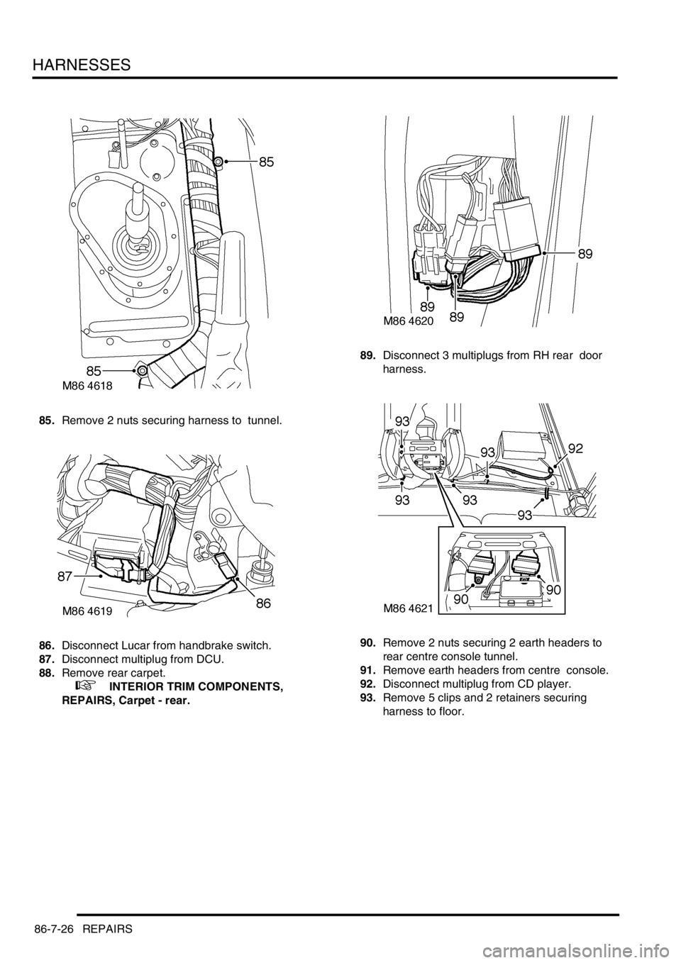
85.Remove 2 nuts securing harness to tunnel.
86.Disconnect Lucar from handbrake switch.
87.Disconnect multiplug from DCU.
88.Remove rear carpet.
+ INTERIOR TRIM COMPONENTS,
REPAIRS, Carpet - rear.89.Disconnect 3 multiplugs from RH rear door
harness.
90.Remove 2 nuts securing 2 earth headers to
rear centre console tunnel.
91.Remove earth headers from centre console.
92.Disconnect multiplug from CD player.
93.Remove 5 clips and 2 retainers securing
harness to floor.
Page 1432 of 1529

HARNESSES
REPAIRS 86-7-27
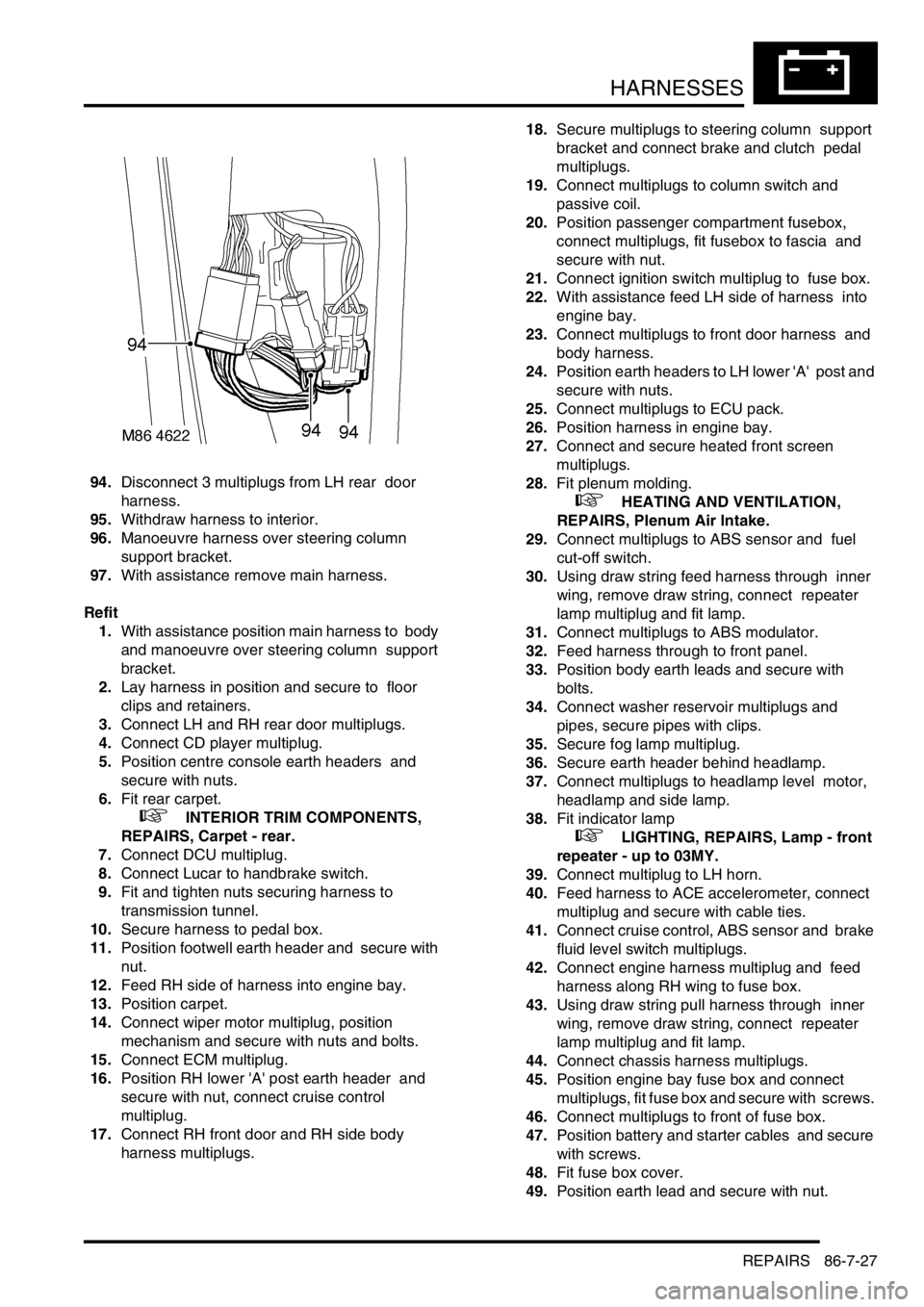
94.Disconnect 3 multiplugs from LH rear door
harness.
95.Withdraw harness to interior.
96.Manoeuvre harness over steering column
support bracket.
97.With assistance remove main harness.
Refit
1.With assistance position main harness to body
and manoeuvre over steering column support
bracket.
2.Lay harness in position and secure to floor
clips and retainers.
3.Connect LH and RH rear door multiplugs.
4.Connect CD player multiplug.
5.Position centre console earth headers and
secure with nuts.
6.Fit rear carpet.
+ INTERIOR TRIM COMPONENTS,
REPAIRS, Carpet - rear.
7.Connect DCU multiplug.
8.Connect Lucar to handbrake switch.
9.Fit and tighten nuts securing harness to
transmission tunnel.
10.Secure harness to pedal box.
11.Position footwell earth header and secure with
nut.
12.Feed RH side of harness into engine bay.
13.Position carpet.
14.Connect wiper motor multiplug, position
mechanism and secure with nuts and bolts.
15.Connect ECM multiplug.
16.Position RH lower 'A' post earth header and
secure with nut, connect cruise control
multiplug.
17.Connect RH front door and RH side body
harness multiplugs. 18.Secure multiplugs to steering column support
bracket and connect brake and clutch pedal
multiplugs.
19.Connect multiplugs to column switch and
passive coil.
20.Position passenger compartment fusebox,
connect multiplugs, fit fusebox to fascia and
secure with nut.
21.Connect ignition switch multiplug to fuse box.
22.With assistance feed LH side of harness into
engine bay.
23.Connect multiplugs to front door harness and
body harness.
24.Position earth headers to LH lower 'A' post and
secure with nuts.
25.Connect multiplugs to ECU pack.
26.Position harness in engine bay.
27.Connect and secure heated front screen
multiplugs.
28.Fit plenum molding.
+ HEATING AND VENTILATION,
REPAIRS, Plenum Air Intake.
29.Connect multiplugs to ABS sensor and fuel
cut-off switch.
30.Using draw string feed harness through inner
wing, remove draw string, connect repeater
lamp multiplug and fit lamp.
31.Connect multiplugs to ABS modulator.
32.Feed harness through to front panel.
33.Position body earth leads and secure with
bolts.
34.Connect washer reservoir multiplugs and
pipes, secure pipes with clips.
35.Secure fog lamp multiplug.
36.Secure earth header behind headlamp.
37.Connect multiplugs to headlamp level motor,
headlamp and side lamp.
38.Fit indicator lamp
+ LIGHTING, REPAIRS, Lamp - front
repeater - up to 03MY.
39.Connect multiplug to LH horn.
40.Feed harness to ACE accelerometer, connect
multiplug and secure with cable ties.
41.Connect cruise control, ABS sensor and brake
fluid level switch multiplugs.
42.Connect engine harness multiplug and feed
harness along RH wing to fuse box.
43.Using draw string pull harness through inner
wing, remove draw string, connect repeater
lamp multiplug and fit lamp.
44.Connect chassis harness multiplugs.
45.Position engine bay fuse box and connect
multiplugs, fit fuse box and secure with screws.
46.Connect multiplugs to front of fuse box.
47.Position battery and starter cables and secure
with screws.
48.Fit fuse box cover.
49.Position earth lead and secure with nut.