Page 1484 of 1529

INSTRUMENTS
DESCRIPTION AND OPERATION 88-1
INS TRUMENTS DESCRIPTION AND OPERAT ION
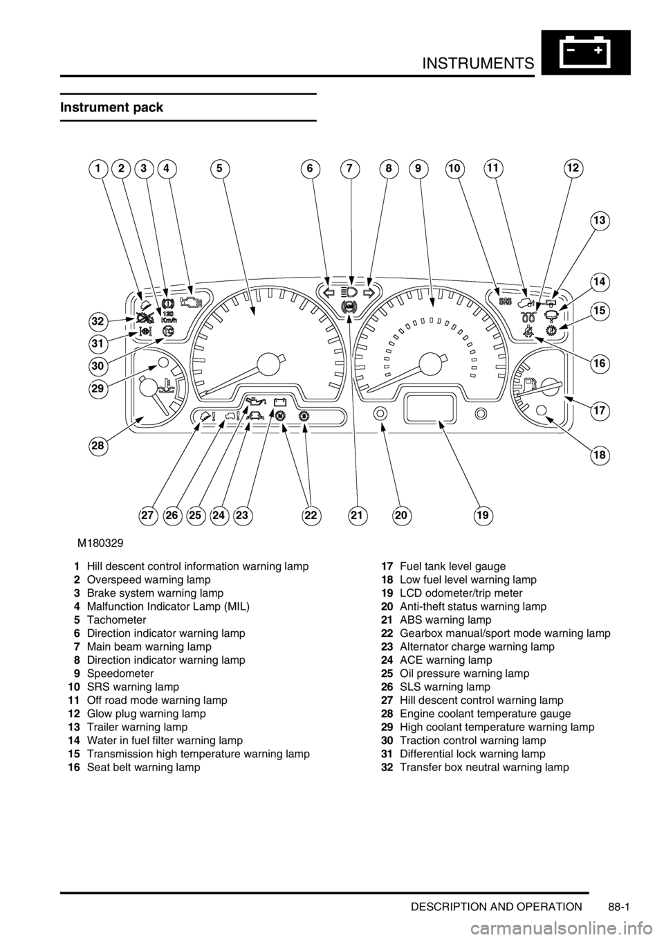
Instrument pack
1Hill descent control information warning lamp
2Overspeed warning lamp
3Brake system warning lamp
4Malfunction Indicator Lamp (MIL)
5Tachometer
6Direction indicator warning lamp
7Main beam warning lamp
8Direction indicator warning lamp
9Speedometer
10SRS warning lamp
11Off road mode warning lamp
12Glow plug warning lamp
13Trailer warning lamp
14Water in fuel filter warning lamp
15Transmission high temperature warning lamp
16Seat belt warning lamp17Fuel tank level gauge
18Low fuel level warning lamp
19LCD odometer/trip meter
20Anti-theft status warning lamp
21ABS warning lamp
22Gearbox manual/sport mode warning lamp
23Alternator charge warning lamp
24ACE warning lamp
25Oil pressure warning lamp
26SLS warning lamp
27Hill descent control warning lamp
28Engine coolant temperature gauge
29High coolant temperature warning lamp
30Traction control warning lamp
31Differential lock warning lamp
32Transfer box neutral warning lamp
Page 1485 of 1529
INSTRUMENTS
88-2 DESCRIPTION AND OPERATION
Instrument component location - Engine
compartment / underneath vehicle
1ECM (diesel models)
2Alternator
3Glow plugs
4Transmission temperature sensor
5Water in fuel filter sensor
6Fuel tank sender unit
7Differential lock switch – vehicles up to 03
model year8Differential lock switches – vehicles from 03
model year (where fitted)
9Parking brake switch
10Brake fluid level switch
11Oil pressure switch
Page 1487 of 1529
INSTRUMENTS
88-4 DESCRIPTION AND OPERATION
Instrument block diagram
1Instrument pack
2ECM
3Brake fluid level switch
4Parking brake switch
5Oil pressure switch
6Alternator
7Fuel tank sender unit
8Water in fuel filter sensor
9Transmission temperature sensor
10Differential lock switch - vehicles up to 03
model year or Differential lock switches -
vehicles from 03 model year11Audible warning speaker
12SRS DCU
13SLABS ECU
14BCU
15ACE ECU
16EAT ECU
17Diagnostic connector
18Serial communications link
Page 1489 of 1529

INSTRUMENTS
88-6 DESCRIPTION AND OPERATION
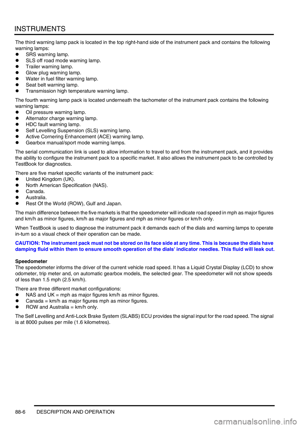
The third warning lamp pack is located in the top right-hand side of the instrument pack and contains the following
warning lamps:
lSRS warning lamp.
lSLS off road mode warning lamp.
lTrailer warning lamp.
lGlow plug warning lamp.
lWater in fuel filter warning lamp.
lSeat belt warning lamp.
lTransmission high temperature warning lamp.
The fourth warning lamp pack is located underneath the tachometer of the instrument pack contains the following
warning lamps:
lOil pressure warning lamp.
lAlternator charge warning lamp.
lHDC fault warning lamp.
lSelf Levelling Suspension (SLS) warning lamp.
lActive Cornering Enhancement (ACE) warning lamp.
lGearbox manual/sport mode warning lamps.
The serial communication link is used to allow information to travel to and from the instrument pack, and it provides
the ability to configure the instrument pack to a specific market. It also allows the instrument pack to be controlled by
TestBook for diagnostics.
There are five market specific variants of the instrument pack:
lUnited Kingdom (UK).
lNorth American Specification (NAS).
lCanada.
lAustralia.
lRest Of the World (ROW), Gulf and Japan.
The main difference between the five markets is that the speedometer will indicate road speed in mph as major figures
and km/h as minor figures, km/h as major figures and mph as minor figures or km/h only.
When TestBook is used to diagnose the instrument pack it demands each of the dials and warning lamps to operate
in-turn so a visual check of their operation can be made.
CAUTION: The instrument pack must not be stored on its face side at any time. This is because the dials have
damping fluid within them to ensure smooth operation of the dials' indicator needles. This fluid will leak out.
Speedometer
The speedometer informs the driver of the current vehicle road speed. It has a Liquid Crystal Display (LCD) to show
odometer, trip meter and, on automatic gearbox models, the selected gear. The speedometer will not show speeds
of less than 1.5 mph (2.5 km/h).
There are three different market configurations:
lNAS and UK = mph as major figures km/h as minor figures.
lCanada = km/h as major figures mph as minor figures.
lROW and Australia = km/h only.
The Self Levelling and Anti-Lock Brake System (SLABS) ECU provides the signal input for the road speed. The signal
is at 8000 pulses per mile (1.6 kilometres).
Page 1512 of 1529
INSTRUMENTS
DESCRIPTION AND OPERATION 88-29
Water in fuel filter warning lamp
The water in fuel filter warning lamp within the instrument pack utilises an amber LED and a clear legend. On vehicles
with diesel engines the LED is illuminated when the water sensor detects water is present in the fuel filter, providing
the driver with a visible warning.
When the ignition is switched on, the instrument pack illuminates the LED to provide a self-check, providing there is
no water present in the fuel filter it will remain illuminated for 3 seconds or until the ignition is switched off.
The power input for the LED is supplied by the instrument pack via fuse 27. The water sensor provides the earth path
to illuminate the warning lamp. The voltage on the earth path from the sensor to the instrument pack is as follows:
l< 1.8 volts = warning lamp on.
l> 7.7 volts = warning lamp off.
Page 1513 of 1529
INSTRUMENTS
88-30 DESCRIPTION AND OPERATION
Water sensor
On vehicles with diesel engines a water sensor is located in the bottom of the fuel filter. The sensor utilises the
different resistance properties between water and diesel fuel to determines the presence of water in the fuel.
The sensor receives a battery voltage supply from the fuel pump relay. The sensor output is supplied to the instrument
pack. The water sensor provides the earth path to illuminate the warning lamp.
l< 1.8 volts = warning lamp on.
l> 7.7 volts = warning lamp off.