Page 993 of 1529

SCREENS
76-4-4 REPAIRS
15.Apply a continuous bead of sealant to sealant
face on screen as shown.
16.With assistance, lift screen into place and align
to screen supports and tape. Ensure top
finisher is located into correct position. Lightly
press glass to fully seat sealer.
CAUTION: Do not apply heavy pressure to
the sides of the windscreen. Lightly press
windscreen from centre outwards until
edges are to required gap. Pushing sides
into position can bend windscreen and lead
to cracking in service.
17.Remove protective covers and tape.
18.Test sealer for leaks, apply additional sealer if
necessary. If water is used, allow sealer to dry
before testing. Spray water around glass and
check for leaks. Mark any area that leaks. Dry
glass and sealer then apply additional sealer.
19.Fit interior mirror to slug.
20.If applicable, connect screen heater multiplugs.
21.Fit air intake plenum.
+ HEATING AND VENTILATION,
REPAIRS, Plenum Air Intake.
CAUTION: A curing time of 6 hours is
desirable. During this time leave a window
open to ventilate the vehicle interior. If the
vehicle must be used before the curing time
has elapsed, do not drive at speed or slam
the doors with the windows closed.
CAUTION: Vehicles fitted with a passenger
airbag should not be driven for 24 hours.
Glass - body side - rear
$% 76.81.18
Introduction
The following equipment is required:
lCutting wire and handles.
lKent cutting knife.
lGlazing knife.
lWindscreen repair kit.
lSealant applicator gun.
lSuction cups.
lA felt covered table or stand to support glass.
WARNING: Wear protective gloves when
handling glass, solvents and primers.
WARNING: Wear suitable eye protection when
removing and refitting glass.
Remove
1.If fitted, disconnect coaxial cable from terminal
on glass.
2.Fit protection to exterior body work adjacent to
glass.
3.Cover body panels adjacent to glass.
4.Fit protection to internal trim adjacent to glass.
5.Cover interior of vehicle with protective sheet.
Page 1018 of 1529

SEATS
REPAIRS 76-5-21
Refit
1.Fit cover to cushion.
2.Fit and clamp hog rings securing cover to
cushion.
3.Fit outer edges of cover over cushion.
4.Fit cushion and cover assembly to seat frame.
5. Models with seat heaters: Connect seat
heater multiplug.
6.Secure rear edge of cushion cover with clip.
7.Fit end clips over rear edge of cushion cover.
8.Secure lower edge of squab cover to seat
frame.
9.Secure edges of cushion cover with clips.
10.Secure front edge of cushion cover with clip.
11.Position seat correct way up on work bench.
12.Secure inner edge trim casing to seat frame.
13.Fit outer edge trim casing to seat frame and
secure with screws.
14.Fit front seat.
+ SEATS, REPAIRS, Seat - front.
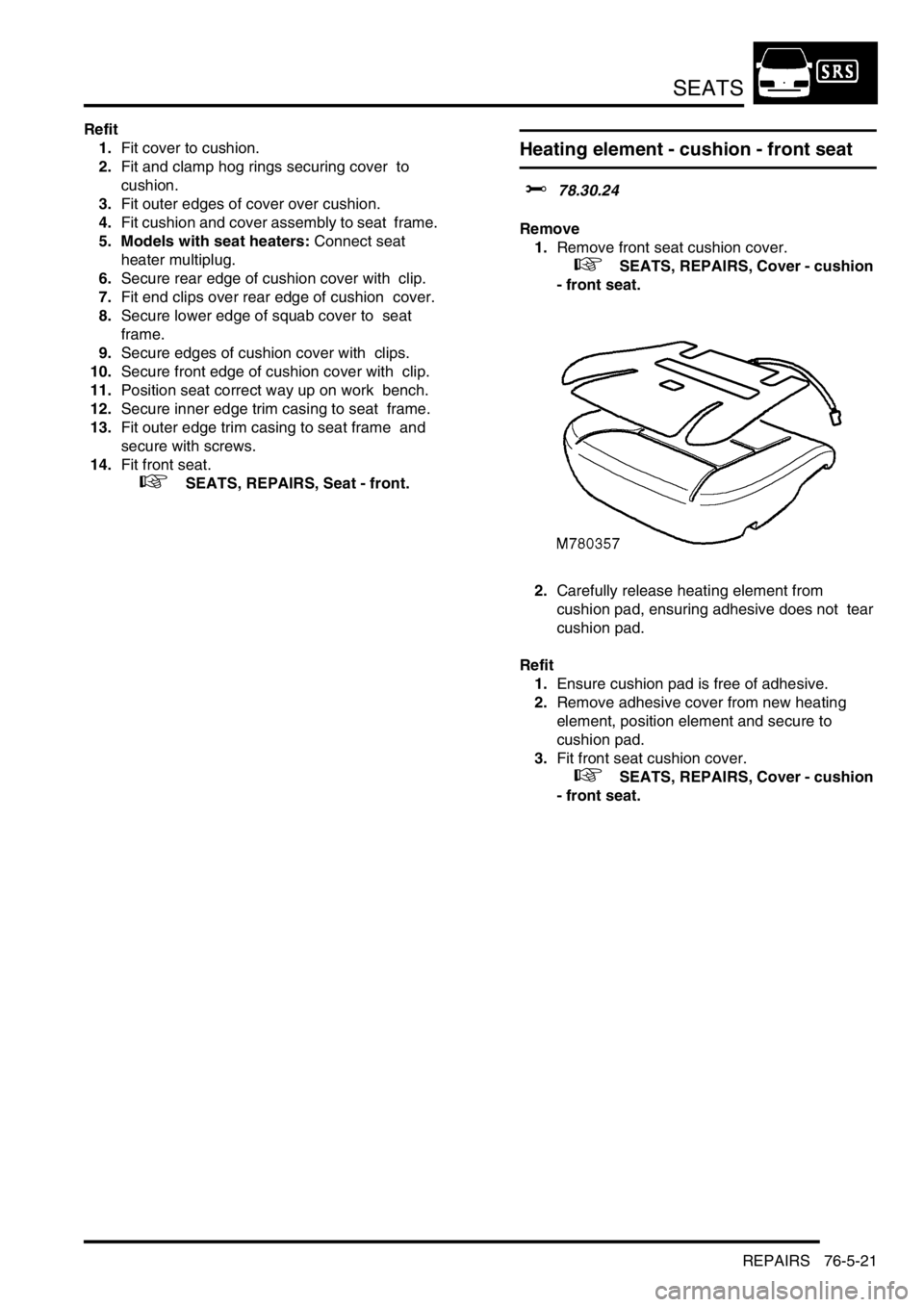
Heating element - cushion - front seat
$% 78.30.24
Remove
1.Remove front seat cushion cover.
+ SEATS, REPAIRS, Cover - cushion
- front seat.
2.Carefully release heating element from
cushion pad, ensuring adhesive does not tear
cushion pad.
Refit
1.Ensure cushion pad is free of adhesive.
2.Remove adhesive cover from new heating
element, position element and secure to
cushion pad.
3.Fit front seat cushion cover.
+ SEATS, REPAIRS, Cover - cushion
- front seat.
Page 1030 of 1529
SEATS
REPAIRS 76-5-33
Heating element - squab - front seat
$% 78.90.36
Remove
1.Remove front seat squab cover.
+ SEATS, REPAIRS, Cover - squab -
front seat.
2.Disconnect heating element multiplug.
3.Carefully release heating element from squab
pad, ensuring adhesive does not tear squab
pad.
Refit
1.Ensure squab pad is free of adhesive.
2.Remove adhesive cover from new heating
element, position element and secure to squab
pad.
3.Fit front seat squab cover.
+ SEATS, REPAIRS, Cover - squab -
front seat.
Head restraint - third row seat
$% 78.50.10
Remove
1.Fold down both third row head restaints.
2.Release upper tail gate finisher from 6 clips and
remove finisher.
3.Remove 3 bolts securing head restraint and
remove head restraint.
Refit
1.Position head restraint, fit and tighten bolts.
2.Position upper tail gate finisher and secure in
clips.
M78 0493
M78 0494
Page 1158 of 1529
HEATING AND VENTILATION
DESCRIPTION AND OPERATION 80-1
HEATING A ND VENT ILATION DESCRIPTION AND OPERAT ION
Heating and ventilation component
layout
RH drive shown, LH drive similar
1Control panel
2Outlet vent
3Rear footwell ducts4Front footwell duct
5Air inlet duct
6Heater assembly
Page 1159 of 1529
HEATING AND VENTILATION
80-2DESCRIPTION AND OPERATION
Fuel burning heater component layout
RH drive shown, LH drive similar
1FBH fuel line connection
2FBH unit3Air temperature sensor
4FBH pump
Page 1160 of 1529
HEATING AND VENTILATION
DESCRIPTION AND OPERATION 80-3
Description
General
The heating and ventilation system controls the temperature and distribution of air supplied to the vehicle interior. The
system consists of an air inlet duct, heater assembly, distribution ducts and a control panel. An outlet vent is
incorporated at the rear of the cabin. Some diesel models also incorporate a fuel burning heater (FBH) system in the
engine coolant supply to the heater assembly.
Fresh or recirculated air flows into the heater assembly from the inlet duct. An electrical variable speed blower in the
inlet duct, and/or ram effect, forces the air through the system. Depending on the settings on the control panel, the air
is then heated and supplied through the distribution ducts to fascia and floor level outlets.
Page 1161 of 1529

HEATING AND VENTILATION
80-4DESCRIPTION AND OPERATION
Air inlet duct
RH drive shown, LH drive similar
1Air outlet
2Resistor pack
3Wiring harness
4Blower
5Blower relay6Recirculated air servo motor
7Control flap operating mechanism
8Recirculated air inlet
9Recirculated air inlet
10Fresh air inlet
The air inlet duct is installed behind the fascia, on the passenger's side. The air inlet duct is connected to the plenum
to provide the fresh air inlet. Two grilles in the air inlet duct provide recirculated air inlets from the cabin. Two control
flaps, operated by a servo motor, open and close the fresh and recirculated air inlets to control the source of incoming
air. Operation of the servo motor is controlled by a switch on the control panel.
The blower is installed between the air inlets and the outlet to the heater assembly, and consists of an open hub,
centrifugal fan powered by an electric motor. Operation of the blower is controlled by a slider switch on the control
panel, via a blower relay mounted on the air inlet duct and a resistor pack. The resistor pack is installed in the air outlet
from the blower fan, so that any heat generated is dissipated by the air flow. A wiring harness on the air inlet duct
connects the servo motor, blower motor, blower relay and resistor pack to the vehicle wiring.
Page 1162 of 1529

HEATING AND VENTILATION
DESCRIPTION AND OPERATION 80-5
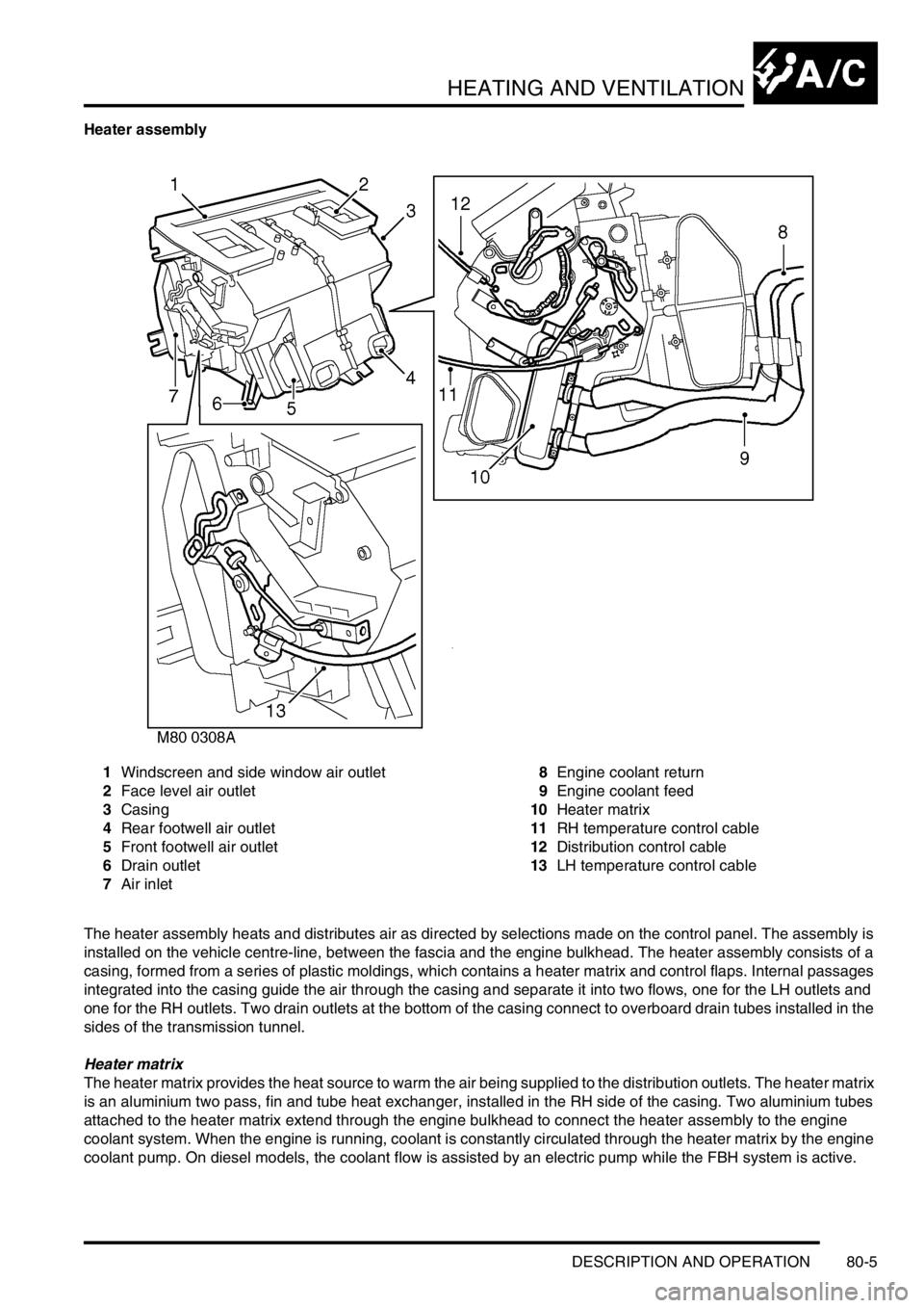
Heater assembly
1Windscreen and side window air outlet
2Face level air outlet
3Casing
4Rear footwell air outlet
5Front footwell air outlet
6Drain outlet
7Air inlet8Engine coolant return
9Engine coolant feed
10Heater matrix
11RH temperature control cable
12Distribution control cable
13LH temperature control cable
The heater assembly heats and distributes air as directed by selections made on the control panel. The assembly is
installed on the vehicle centre-line, between the fascia and the engine bulkhead. The heater assembly consists of a
casing, formed from a series of plastic moldings, which contains a heater matrix and control flaps. Internal passages
integrated into the casing guide the air through the casing and separate it into two flows, one for the LH outlets and
one for the RH outlets. Two drain outlets at the bottom of the casing connect to overboard drain tubes installed in the
sides of the transmission tunnel.
Heater matrix
The heater matrix provides the heat source to warm the air being supplied to the distribution outlets. The heater matrix
is an aluminium two pass, fin and tube heat exchanger, installed in the RH side of the casing. Two aluminium tubes
attached to the heater matrix extend through the engine bulkhead to connect the heater assembly to the engine
coolant system. When the engine is running, coolant is constantly circulated through the heater matrix by the engine
coolant pump. On diesel models, the coolant flow is assisted by an electric pump while the FBH system is active.