1999 LAND ROVER DISCOVERY heating
[x] Cancel search: heatingPage 1227 of 1529
AIR CONDITIONING
82-38REPAIRS
Evaporator, evaporator thermistor and
thermal expansion valve (TXV)
$% 82.25.20
Remove
1.Remove heater assembly.
+ HEATING AND VENTILATION,
REPAIRS, Heater assembly - models with
air conditioning.
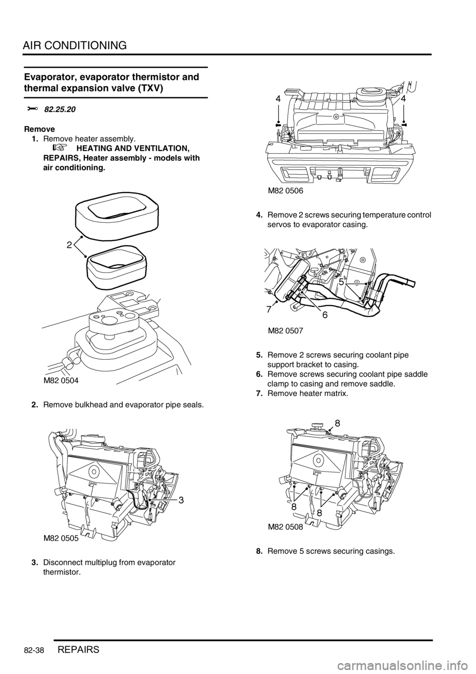
2.Remove bulkhead and evaporator pipe seals.
3.Disconnect multiplug from evaporator
thermistor. 4.Remove 2 screws securing temperature control
servos to evaporator casing.
5.Remove 2 screws securing coolant pipe
support bracket to casing.
6.Remove screws securing coolant pipe saddle
clamp to casing and remove saddle.
7.Remove heater matrix.
8.Remove 5 screws securing casings.
Page 1229 of 1529
AIR CONDITIONING
82-40REPAIRS
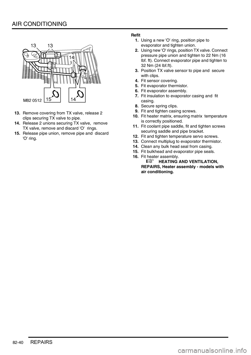
13.Remove covering from TX valve, release 2
clips securing TX valve to pipe.
14.Release 2 unions securing TX valve, remove
TX valve, remove and discard 'O' rings.
15.Release pipe union, remove pipe and discard
'O' ring. Refit
1.Using a new 'O' ring, position pipe to
evaporator and tighten union.
2.Using new 'O' rings, position TX valve. Connect
pressure pipe union and tighten to 22 Nm (16
lbf. ft). Connect evaporator pipe and tighten to
32 Nm (24 lbf.ft).
3.Position TX valve sensor to pipe and secure
with clips.
4.Fit sensor covering.
5.Fit evaporator thermistor.
6.Fit evaporator assembly.
7.Fit insulation to evaporator casing and fit
casing.
8.Secure spring clips.
9.Fit and tighten casing screws.
10.Fit heater matrix, ensuring matrix temperature
is correctly positioned.
11.Fit coolant pipe saddle, fit and tighten screws
securing saddle and pipe bracket.
12.Fit and tighten temperature servo screws.
13.Connect multiplug to evaporator thermistor.
14.Clean any bulk head seal from casing.
15.Fit bulkhead and evaporator pipe seals.
16.Fit heater assembly.
+ HEATING AND VENTILATION,
REPAIRS, Heater assembly - models with
air conditioning.
Page 1260 of 1529
WIPERS AND WASHERS
REPAIRS 84-25
Motor and linkage - wiper - windscreen
$% 84.15.11
Remove
1.Remove plenum air intake.
+ HEATING AND VENTILATION,
REPAIRS, Plenum Air Intake.
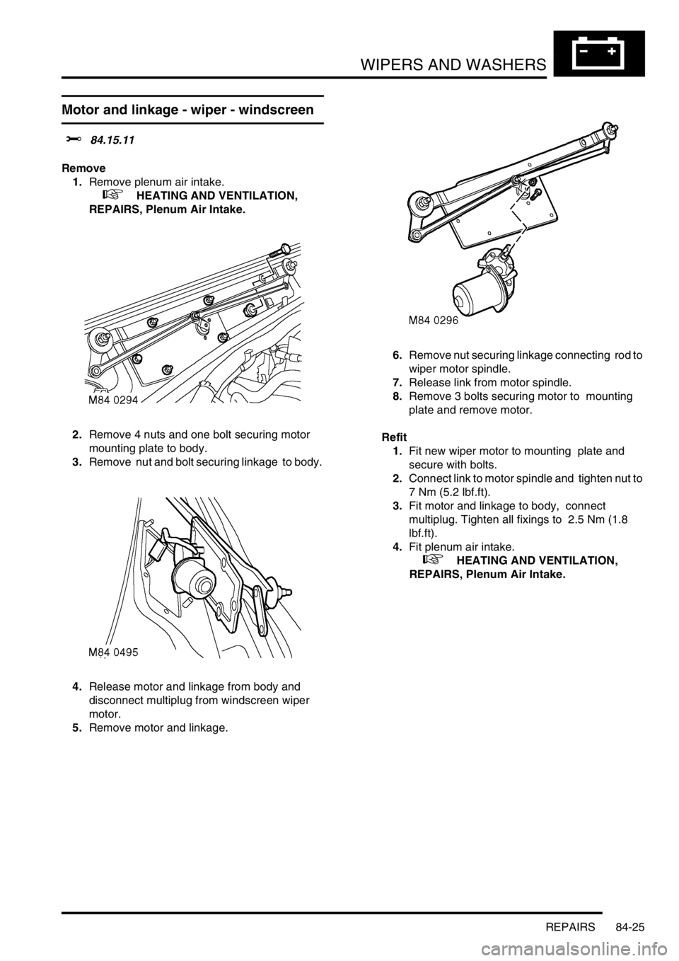
2.Remove 4 nuts and one bolt securing motor
mounting plate to body.
3.Remove nut and bolt securing linkage to body.
4.Release motor and linkage from body and
disconnect multiplug from windscreen wiper
motor.
5.Remove motor and linkage. 6.Remove nut securing linkage connecting rod to
wiper motor spindle.
7.Release link from motor spindle.
8.Remove 3 bolts securing motor to mounting
plate and remove motor.
Refit
1.Fit new wiper motor to mounting plate and
secure with bolts.
2.Connect link to motor spindle and tighten nut to
7 Nm (5.2 lbf.ft).
3.Fit motor and linkage to body, connect
multiplug. Tighten all fixings to 2.5 Nm (1.8
lbf.ft).
4.Fit plenum air intake.
+ HEATING AND VENTILATION,
REPAIRS, Plenum Air Intake.
Page 1420 of 1529
HARNESSES
REPAIRS 86-7-15
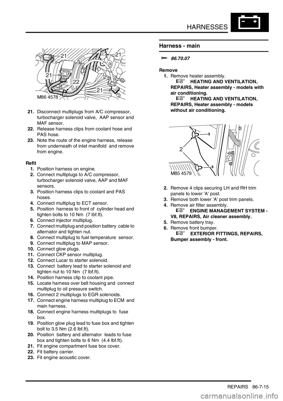
21.Disconnect multiplugs from A/C compressor,
turbocharger solenoid valve, AAP sensor and
MAF sensor.
22.Release harness clips from coolant hose and
PAS hose.
23.Note the route of the engine harness, release
from underneath of inlet manifold and remove
from engine.
Refit
1.Position harness on engine.
2.Connect multiplugs to A/C compressor,
turbocharger solenoid valve, AAP and MAF
sensors.
3.Position harness clips to coolant and PAS
hoses.
4.Connect multiplug to ECT sensor.
5.Position harness to front of cylinder head and
tighten bolts to 10 Nm (7 lbf.ft).
6.Connect injector multiplug.
7.Connect multiplug and position battery cable to
alternator and tighten nut.
8.Connect multiplug to fuel temperature sensor.
9.Connect multiplug to MAP sensor.
10.Connect glow plugs.
11.Connect CKP sensor multiplug.
12.Connect Lucar to starter solenoid.
13.Connect battery lead to starter solenoid and
tighten nut to 10 Nm (7 lbf.ft).
14.Position harness clip to coolant pipe.
15.Locate harness over bell housing and connect
multiplug to oil pressure switch.
16.Connect 2 multiplugs to EGR solenoids.
17.Connect engine harness multiplug to ECM and
main harness.
18.Connect engine harness multiplugs to fuse
box.
19.Position glow plug lead to fuse box and tighten
bolt to 3.5 Nm (2.6 lbf.ft).
20.Position battery and alternator leads to fuse
box and tighten bolts to 6 Nm (4.4 lbf.ft).
21.Fit engine compartment fuse box cover.
22.Fit battery carrier.
23.Fit engine acoustic cover.
Harness - main
$% 86.70.07
Remove
1.Remove heater assembly.
+ HEATING AND VENTILATION,
REPAIRS, Heater assembly - models with
air conditioning.
+ HEATING AND VENTILATION,
REPAIRS, Heater assembly - models
without air conditioning.
2.Remove 4 clips securing LH and RH trim
panels to lower 'A' post.
3.Remove both lower 'A' post trim panels.
4.Remove air filter assembly.
+ ENGINE MANAGEMENT SYSTEM -
V8, REPAIRS, Air cleaner assembly.
5.Remove battery tray.
6.Remove front bumper.
+ EXTERIOR FITTINGS, REPAIRS,
Bumper assembly - front.
Page 1426 of 1529
HARNESSES
REPAIRS 86-7-21
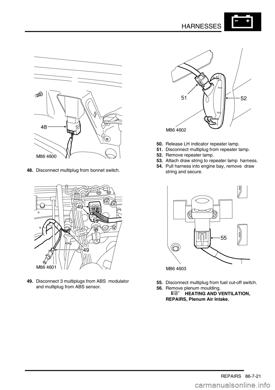
48.Disconnect multiplug from bonnet switch.
49.Disconnect 3 multiplugs from ABS modulator
and multiplug from ABS sensor. 50.Release LH indicator repeater lamp.
51.Disconnect multiplug from repeater lamp.
52.Remove repeater lamp.
53.Attach draw string to repeater lamp harness.
54.Pull harness into engine bay, remove draw
string and secure.
55.Disconnect multiplug from fuel cut-off switch.
56.Remove plenum moulding.
+ HEATING AND VENTILATION,
REPAIRS, Plenum Air Intake.
Page 1432 of 1529
HARNESSES
REPAIRS 86-7-27
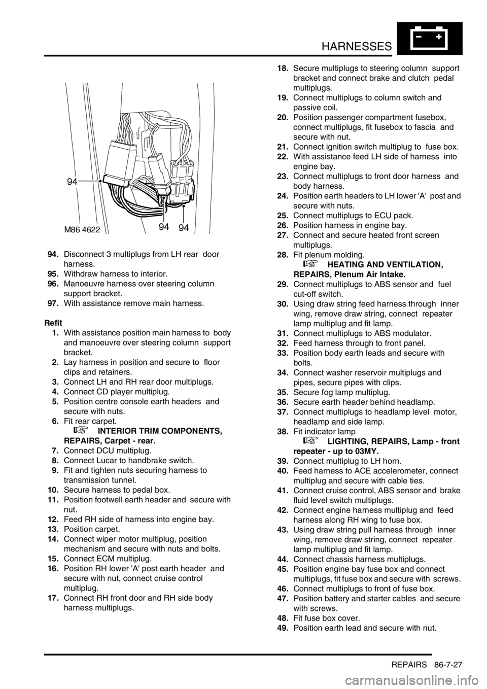
94.Disconnect 3 multiplugs from LH rear door
harness.
95.Withdraw harness to interior.
96.Manoeuvre harness over steering column
support bracket.
97.With assistance remove main harness.
Refit
1.With assistance position main harness to body
and manoeuvre over steering column support
bracket.
2.Lay harness in position and secure to floor
clips and retainers.
3.Connect LH and RH rear door multiplugs.
4.Connect CD player multiplug.
5.Position centre console earth headers and
secure with nuts.
6.Fit rear carpet.
+ INTERIOR TRIM COMPONENTS,
REPAIRS, Carpet - rear.
7.Connect DCU multiplug.
8.Connect Lucar to handbrake switch.
9.Fit and tighten nuts securing harness to
transmission tunnel.
10.Secure harness to pedal box.
11.Position footwell earth header and secure with
nut.
12.Feed RH side of harness into engine bay.
13.Position carpet.
14.Connect wiper motor multiplug, position
mechanism and secure with nuts and bolts.
15.Connect ECM multiplug.
16.Position RH lower 'A' post earth header and
secure with nut, connect cruise control
multiplug.
17.Connect RH front door and RH side body
harness multiplugs. 18.Secure multiplugs to steering column support
bracket and connect brake and clutch pedal
multiplugs.
19.Connect multiplugs to column switch and
passive coil.
20.Position passenger compartment fusebox,
connect multiplugs, fit fusebox to fascia and
secure with nut.
21.Connect ignition switch multiplug to fuse box.
22.With assistance feed LH side of harness into
engine bay.
23.Connect multiplugs to front door harness and
body harness.
24.Position earth headers to LH lower 'A' post and
secure with nuts.
25.Connect multiplugs to ECU pack.
26.Position harness in engine bay.
27.Connect and secure heated front screen
multiplugs.
28.Fit plenum molding.
+ HEATING AND VENTILATION,
REPAIRS, Plenum Air Intake.
29.Connect multiplugs to ABS sensor and fuel
cut-off switch.
30.Using draw string feed harness through inner
wing, remove draw string, connect repeater
lamp multiplug and fit lamp.
31.Connect multiplugs to ABS modulator.
32.Feed harness through to front panel.
33.Position body earth leads and secure with
bolts.
34.Connect washer reservoir multiplugs and
pipes, secure pipes with clips.
35.Secure fog lamp multiplug.
36.Secure earth header behind headlamp.
37.Connect multiplugs to headlamp level motor,
headlamp and side lamp.
38.Fit indicator lamp
+ LIGHTING, REPAIRS, Lamp - front
repeater - up to 03MY.
39.Connect multiplug to LH horn.
40.Feed harness to ACE accelerometer, connect
multiplug and secure with cable ties.
41.Connect cruise control, ABS sensor and brake
fluid level switch multiplugs.
42.Connect engine harness multiplug and feed
harness along RH wing to fuse box.
43.Using draw string pull harness through inner
wing, remove draw string, connect repeater
lamp multiplug and fit lamp.
44.Connect chassis harness multiplugs.
45.Position engine bay fuse box and connect
multiplugs, fit fuse box and secure with screws.
46.Connect multiplugs to front of fuse box.
47.Position battery and starter cables and secure
with screws.
48.Fit fuse box cover.
49.Position earth lead and secure with nut.
Page 1433 of 1529
HARNESSES
86-7-28 REPAIRS
50.Feed harness through to front panel.
51.Secure fog lamp multiplug.
52.Connect headlamp level motor, headlamp and
side lamp multiplugs.
53.Fit indicator lamp.
+ LIGHTING, REPAIRS, Lamp - front
repeater - up to 03MY.
54.Secure harness to RH front panel.
55.Connect cooling fan and horn multiplug.
56.Secure harness to lower support rail.
57.Connect receiver drier and air temperature
sensor multiplugs.
58.Fit front bumper.
+ EXTERIOR FITTINGS, REPAIRS,
Bumper assembly - front.
59.Fit battery tray.
60.Fit air filter assembly.
+ ENGINE MANAGEMENT SYSTEM -
V8, REPAIRS, Air cleaner assembly.
61.Position both lower 'A' post trims and secure
with studs.
62.Fit heater assembly.
+ HEATING AND VENTILATION,
REPAIRS, Heater assembly - models with
air conditioning.
+ HEATING AND VENTILATION,
REPAIRS, Heater assembly - models
without air conditioning.
Harness - main - DVD unit
$% 86.70.25
Remove
1.Remove battery cover and disconnect the
battery earth lead.
2.Remove CD switch box.
+ IN CAR ENTERTAINMENT,
REPAIRS, Switch box - CD/DVD player.
3.Remove DVD player unit.
+ IN CAR ENTERTAINMENT,
REPAIRS, DVD screen/player unit.
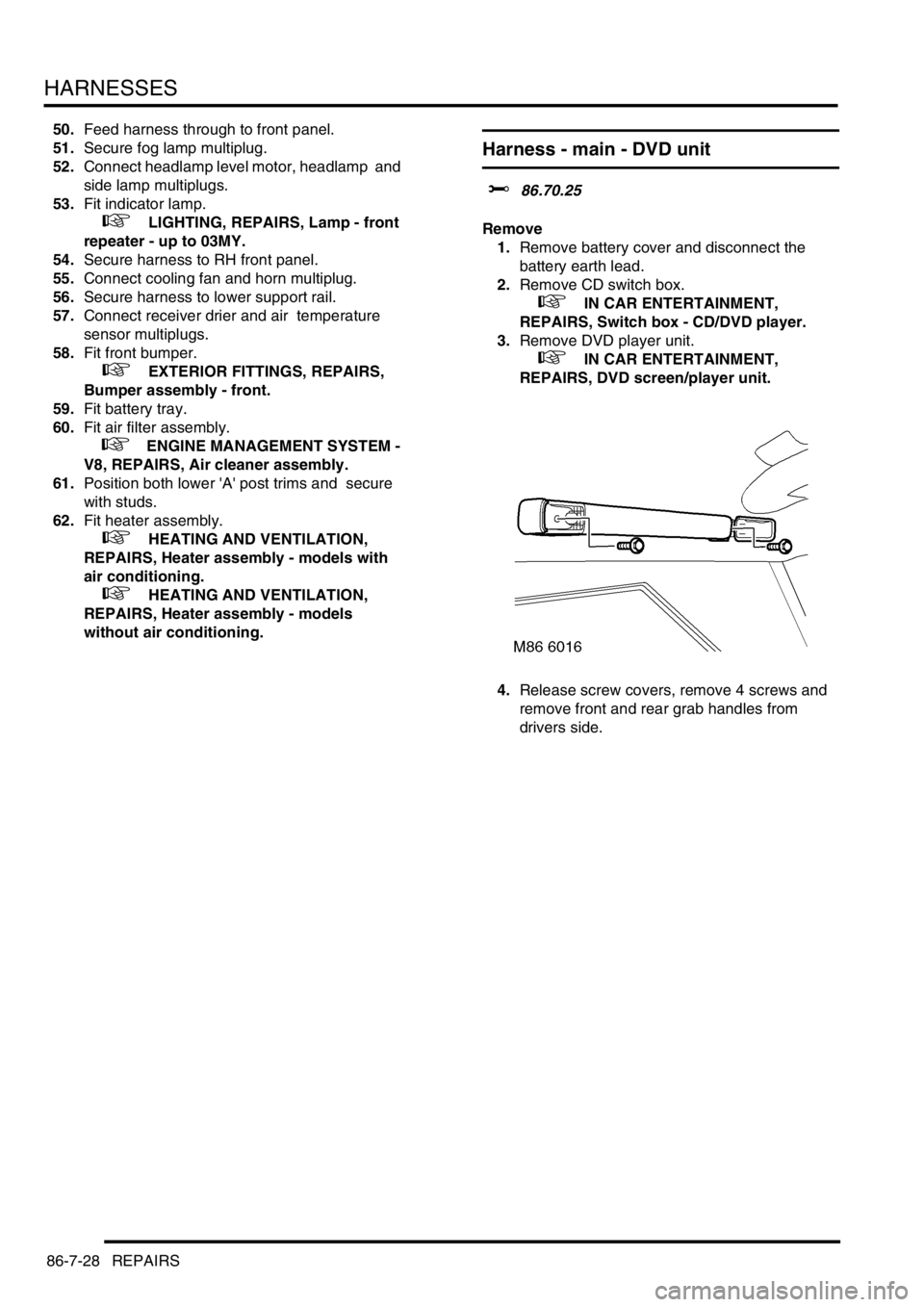
4.Release screw covers, remove 4 screws and
remove front and rear grab handles from
drivers side.
Page 1494 of 1529
INSTRUMENTS
DESCRIPTION AND OPERATION 88-11
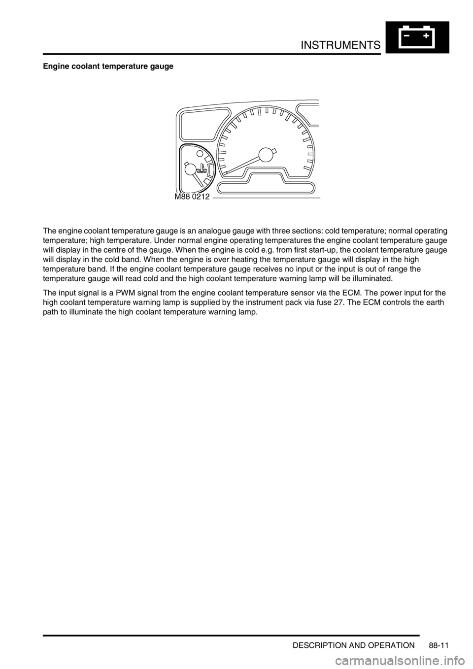
Engine coolant temperature gauge
The engine coolant temperature gauge is an analogue gauge with three sections: cold temperature; normal operating
temperature; high temperature. Under normal engine operating temperatures the engine coolant temperature gauge
will display in the centre of the gauge. When the engine is cold e.g. from first start-up, the coolant temperature gauge
will display in the cold band. When the engine is over heating the temperature gauge will display in the high
temperature band. If the engine coolant temperature gauge receives no input or the input is out of range the
temperature gauge will read cold and the high coolant temperature warning lamp will be illuminated.
The input signal is a PWM signal from the engine coolant temperature sensor via the ECM. The power input for the
high coolant temperature warning lamp is supplied by the instrument pack via fuse 27. The ECM controls the earth
path to illuminate the high coolant temperature warning lamp.