Page 993 of 1529

SCREENS
76-4-4 REPAIRS
15.Apply a continuous bead of sealant to sealant
face on screen as shown.
16.With assistance, lift screen into place and align
to screen supports and tape. Ensure top
finisher is located into correct position. Lightly
press glass to fully seat sealer.
CAUTION: Do not apply heavy pressure to
the sides of the windscreen. Lightly press
windscreen from centre outwards until
edges are to required gap. Pushing sides
into position can bend windscreen and lead
to cracking in service.
17.Remove protective covers and tape.
18.Test sealer for leaks, apply additional sealer if
necessary. If water is used, allow sealer to dry
before testing. Spray water around glass and
check for leaks. Mark any area that leaks. Dry
glass and sealer then apply additional sealer.
19.Fit interior mirror to slug.
20.If applicable, connect screen heater multiplugs.
21.Fit air intake plenum.
+ HEATING AND VENTILATION,
REPAIRS, Plenum Air Intake.
CAUTION: A curing time of 6 hours is
desirable. During this time leave a window
open to ventilate the vehicle interior. If the
vehicle must be used before the curing time
has elapsed, do not drive at speed or slam
the doors with the windows closed.
CAUTION: Vehicles fitted with a passenger
airbag should not be driven for 24 hours.
Glass - body side - rear
$% 76.81.18
Introduction
The following equipment is required:
lCutting wire and handles.
lKent cutting knife.
lGlazing knife.
lWindscreen repair kit.
lSealant applicator gun.
lSuction cups.
lA felt covered table or stand to support glass.
WARNING: Wear protective gloves when
handling glass, solvents and primers.
WARNING: Wear suitable eye protection when
removing and refitting glass.
Remove
1.If fitted, disconnect coaxial cable from terminal
on glass.
2.Fit protection to exterior body work adjacent to
glass.
3.Cover body panels adjacent to glass.
4.Fit protection to internal trim adjacent to glass.
5.Cover interior of vehicle with protective sheet.
Page 1081 of 1529
PANEL REPAIRS
77-2-14 PROCEDURES
Electronic control units
The electronic control units (ECU) fitted to vehicles make it advisable to follow suitable precautions prior to carrying
out welding repair operations. Harsh conditions of heat and vibration may be generated during these operations which
could cause damage to the units.
In particular, it is essential to follow the appropriate precautions when disconnecting or removing the airbag DCU.
Supplementary Restraint System Precautions
Any work undertaken which involves the removal or replacement of any item of the Supplementary Restraint System
(SRS), requires extreme caution and the appropriate precautions must be followed.
+ GENERAL INFORMATION, Supplementary Restraint System Precautions.
Equipment
Prior to commencing any test procedure on the vehicle, ensure that the relevant test equipment is working correctly
and any harness or connectors are in good condition. This particularly applies to electronic control units.
Page 1348 of 1529

ALARM SYSTEM AND HORN
REPAIR 86-4-25
REPAIR
Switch - central door locking
$% 86.26.30
Remove
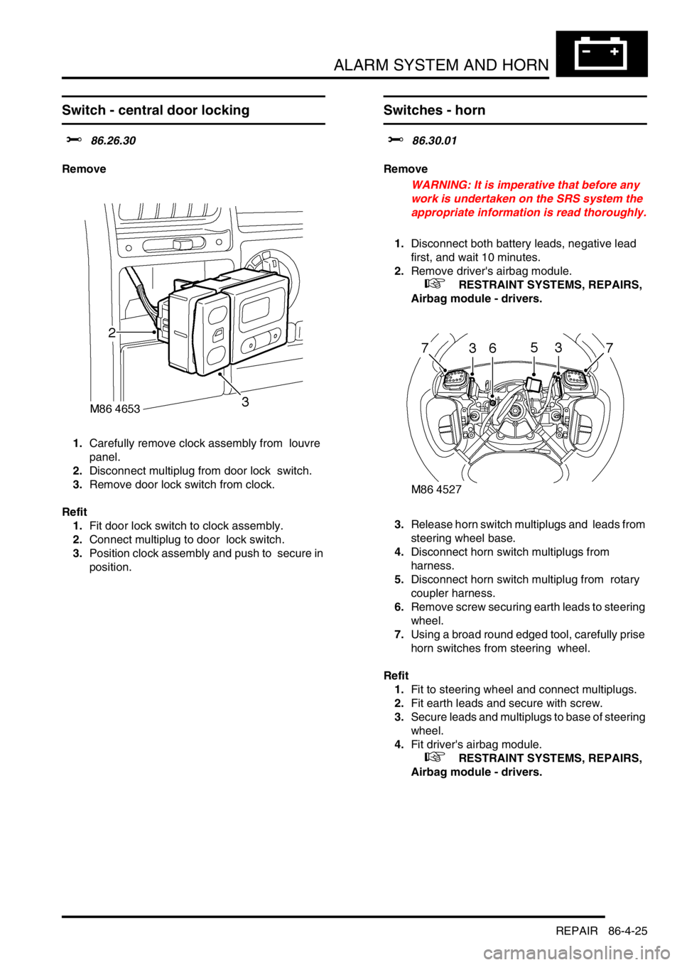
1.Carefully remove clock assembly from louvre
panel.
2.Disconnect multiplug from door lock switch.
3.Remove door lock switch from clock.
Refit
1.Fit door lock switch to clock assembly.
2.Connect multiplug to door lock switch.
3.Position clock assembly and push to secure in
position.
Switches - horn
$% 86.30.01
Remove
WARNING: It is imperative that before any
work is undertaken on the SRS system the
appropriate information is read thoroughly.
1.Disconnect both battery leads, negative lead
first, and wait 10 minutes.
2.Remove driver's airbag module.
+ RESTRAINT SYSTEMS, REPAIRS,
Airbag module - drivers.
3.Release horn switch multiplugs and leads from
steering wheel base.
4.Disconnect horn switch multiplugs from
harness.
5.Disconnect horn switch multiplug from rotary
coupler harness.
6.Remove screw securing earth leads to steering
wheel.
7.Using a broad round edged tool, carefully prise
horn switches from steering wheel.
Refit
1.Fit to steering wheel and connect multiplugs.
2.Fit earth leads and secure with screw.
3.Secure leads and multiplugs to base of steering
wheel.
4.Fit driver's airbag module.
+ RESTRAINT SYSTEMS, REPAIRS,
Airbag module - drivers.
Page 1400 of 1529

IN CAR ENTERTAINMENT
REPAIRS 86-6-33
Switches - remote control - ICE
$% 86.50.13
Remove
1.Remove the key from the starter switch.
Disconnect both battery leads, negative lead
first. Wait ten minutes before starting work.
2.Remove driver's airbag module.
+ RESTRAINT SYSTEMS, REPAIRS,
Airbag module - drivers.
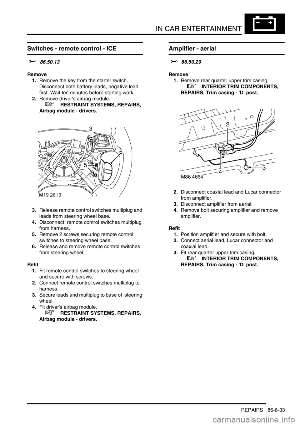
3.Release remote control switches multiplug and
leads from steering wheel base.
4.Disconnect remote control switches multiplug
from harness.
5.Remove 2 screws securing remote control
switches to steering wheel base.
6.Release and remove remote control switches
from steering wheel.
Refit
1.Fit remote control switches to steering wheel
and secure with screws.
2.Connect remote control switches multiplug to
harness.
3.Secure leads and multiplug to base of steering
wheel.
4.Fit driver's airbag module.
+ RESTRAINT SYSTEMS, REPAIRS,
Airbag module - drivers.
Amplifier - aerial
$% 86.50.29
Remove
1.Remove rear quarter upper trim casing.
+ INTERIOR TRIM COMPONENTS,
REPAIRS, Trim casing - 'D' post.
2.Disconnect coaxial lead and Lucar connector
from amplifier.
3.Disconnect amplifier from aerial.
4.Remove bolt securing amplifier and remove
amplifier.
Refit
1.Position amplifier and secure with bolt.
2.Connect aerial lead, Lucar connector and
coaxial lead.
3.Fit rear quarter upper trim casing.
+ INTERIOR TRIM COMPONENTS,
REPAIRS, Trim casing - 'D' post.