1999 LAND ROVER DISCOVERY light
[x] Cancel search: lightPage 116 of 1529

LIFTING AND TOWING
08-3
Remove the propeller shaft fixings, remove the shaft
from the vehicle.
If the front axle is to be trailed turn ignition key to
position '1' to release steering lock.
The steering wheel and/or linkage must be
secured in a straight ahead position. DO NOT use
the steering lock mechanism for this purpose.
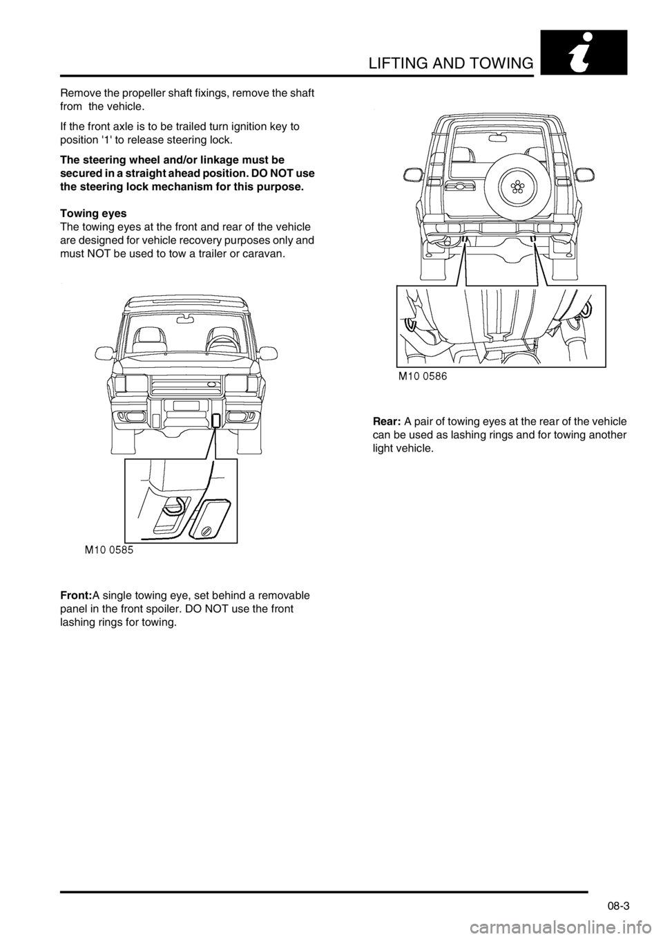
Towing eyes
The towing eyes at the front and rear of the vehicle
are designed for vehicle recovery purposes only and
must NOT be used to tow a trailer or caravan.
Front:A single towing eye, set behind a removable
panel in the front spoiler. DO NOT use the front
lashing rings for towing.Rear: A pair of towing eyes at the rear of the vehicle
can be used as lashing rings and for towing another
light vehicle.
Page 128 of 1529

MAINTENANCE
PROCEDURES 10-5
Lamps, horns and warning indicators
Check
1.Switch on side, head and tail lamps and check
operation.
2.Check headlamp levelling operation.
3.Check turn signals and hazard warning lamps
for correct operation.
4.Press brake pedal and check operation of
brake lamps.
5.Check all exterior lamp lenses for clarity and
condition. Pay particular attention to headlamp
lenses for signs of stone chips or damage.
6.Check horn for loud, clear sound.
7.Switch on headlamps (with ignition switch at 'O'
position) and check light reminder warning
operates when door is opened.
8.Check operation of interior courtesy lights.
9.Check operation of all instrument pack warning
and indicator lights.
Wipers and washers
Check
1. Operate screen washer and switch on wipers.
Ensure washer jets are correctly aimed and
check for smooth, smear free operation of
wiper blades across screen at all speeds
including intermittent.
2.Repeat operation for rear screen washers/
wipers.
3.Check all wiper blades for condition and signs
of splits or damage.
4.Check security of wiper arms.
Page 164 of 1529

ENGINE - V8
DESCRIPTION AND OPERATION 12-2-9
Oil is drawn from the sump through a strainer and into the oil pump via the oil pick-up pipe. Pressurised oil from the
pump passes through the oil cooler (if fitted) mounted in front of the radiator and returns to the full flow oil filter
element. Oil from the filter passes into the main oil gallery and through internal drillings to the crankshaft where it is
directed to each main bearing and to the big-end bearings via numbers 1, 3 and 5 main bearings. An internal drilling
in the cylinder block directs oil to the camshaft where it passes through further internal drillings to the hydraulic
tappets, camshaft bearing journals and rocker shafts. Lubrication to the pistons, small ends and cylinder bores is by
oil grooves machined in the connecting rods and by splash.
Oil pressure switch
The oil pressure warning light switch registers low oil pressure in the main oil gallery on the outflow side of the filter.
Whilst the engine is running and oil pressure is correct, the switch is open. When the ignition is switched on or if oil
pressure drops below the pressure setting of the switch, the switch closes and the low oil pressure warning lamp
located in the instrument pack will illuminate.
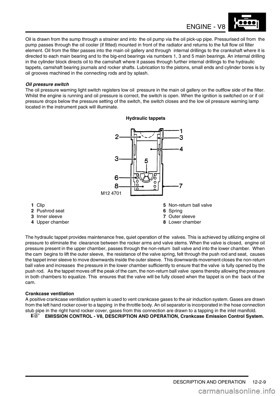
Hydraulic tappets
1Clip
2Pushrod seat
3Inner sleeve
4Upper chamber5Non-return ball valve
6Spring
7Outer sleeve
8Lower chamber
The hydraulic tappet provides maintenance free, quiet operation of the valves. This is achieved by utilizing engine oil
pressure to eliminate the clearance between the rocker arms and valve stems. When the valve is closed, engine oil
pressure present in the upper chamber, passes through the non-return ball valve and into the lower chamber. When
the cam begins to lift the outer sleeve, the resistance of the valve spring, felt through the push rod and seat, causes
the tappet inner sleeve to move downwards inside the outer sleeve. This downwards movement closes the non-return
ball valve and increases the pressure in the lower chamber sufficiently to ensure that the valve is fully opened by the
push rod. As the tappet moves off the peak of the cam, the non-return ball valve opens thereby allowing the pressure
in both chambers to equalize. This ensures that the valve will be fully closed when the tappet is on the back of the
cam.
Crankcase ventilation
A positive crankcase ventilation system is used to vent crankcase gases to the air induction system. Gases are drawn
from the left hand rocker cover to a tapping in the throttle body. An oil separator is incorporated in the hose connection
stub pipe in the right hand rocker cover, gases from this connection are drawn to a tapping in the inlet manifold.
+ EMISSION CONTROL - V8, DESCRIPTION AND OPERATION, Crankcase Emission Control System.
Page 169 of 1529

ENGINE - V8
12-2-14 REPAIRS
Gasket - cylinder head - LH
$% 12.29.02
Remove
1.Remove inlet manifold gasket.
+ MANIFOLDS AND EXHAUST
SYSTEMS - V8, REPAIRS, Gasket - inlet
manifold - lower.
2.Noting their fitted order, disconnect ht leads
from spark plugs.
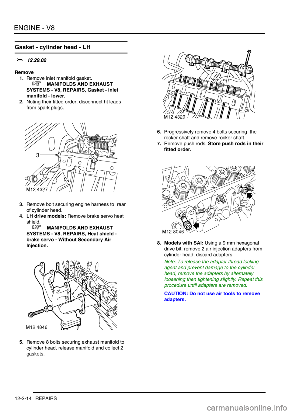
3.Remove bolt securing engine harness to rear
of cylinder head.
4. LH drive models: Remove brake servo heat
shield.
+ MANIFOLDS AND EXHAUST
SYSTEMS - V8, REPAIRS, Heat shield -
brake servo - Without Secondary Air
Injection.
5.Remove 8 bolts securing exhaust manifold to
cylinder head, release manifold and collect 2
gaskets.6.Progressively remove 4 bolts securing the
rocker shaft and remove rocker shaft.
7.Remove push rods. Store push rods in their
fitted order.
8. Models with SAI: Using a 9 mm hexagonal
drive bit, remove 2 air injection adapters from
cylinder head; discard adapters.
Note: To release the adapter thread locking
agent and prevent damage to the cylinder
head, remove the adapters by alternately
loosening then tightening slightly. Repeat this
procedure until adapters are removed.
CAUTION: Do not use air tools to remove
adapters.
Page 170 of 1529

ENGINE - V8
REPAIRS 12-2-15
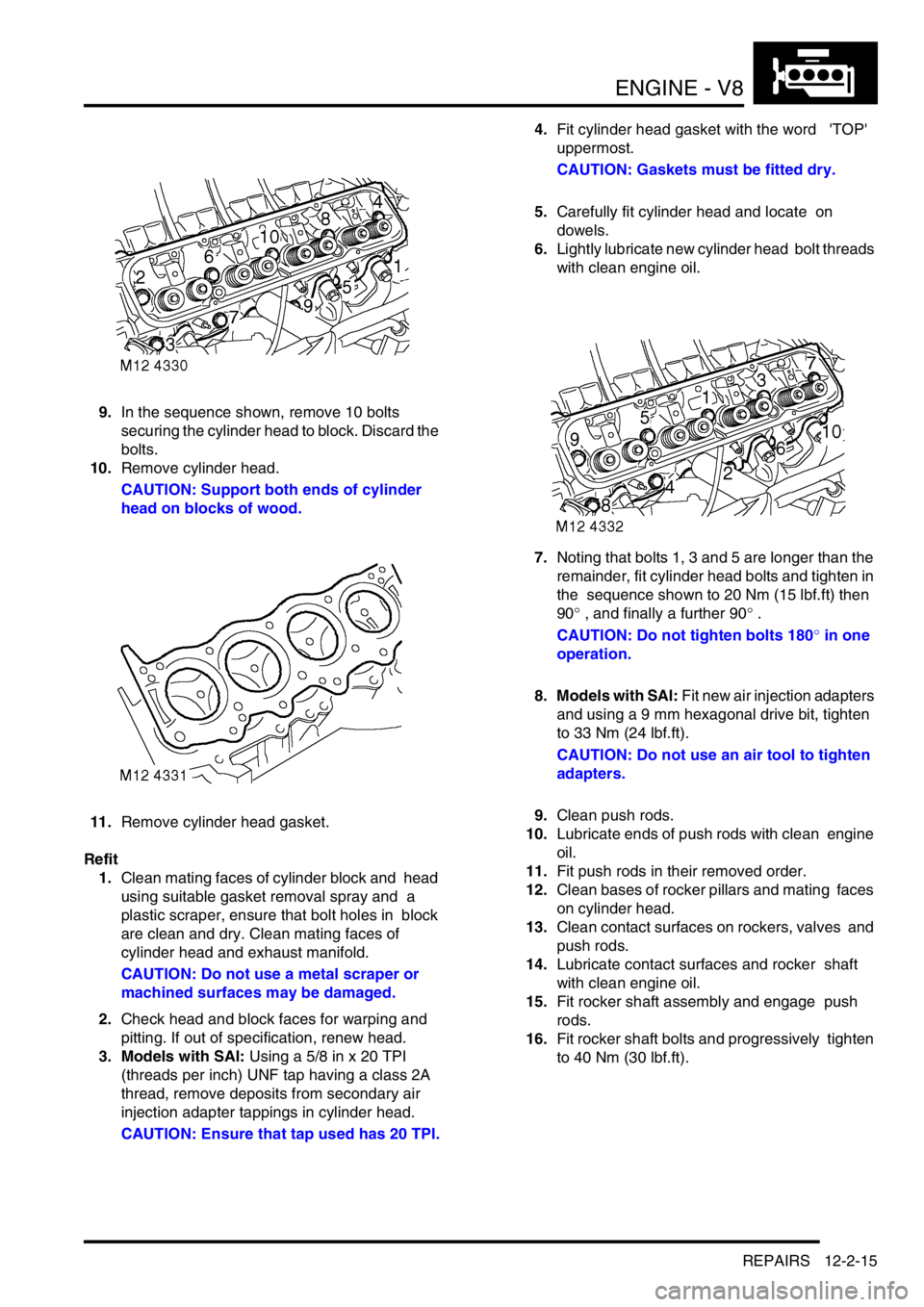
9.In the sequence shown, remove 10 bolts
securing the cylinder head to block. Discard the
bolts.
10.Remove cylinder head.
CAUTION: Support both ends of cylinder
head on blocks of wood.
11.Remove cylinder head gasket.
Refit
1.Clean mating faces of cylinder block and head
using suitable gasket removal spray and a
plastic scraper, ensure that bolt holes in block
are clean and dry. Clean mating faces of
cylinder head and exhaust manifold.
CAUTION: Do not use a metal scraper or
machined surfaces may be damaged.
2.Check head and block faces for warping and
pitting. If out of specification, renew head.
3. Models with SAI: Using a 5/8 in x 20 TPI
(threads per inch) UNF tap having a class 2A
thread, remove deposits from secondary air
injection adapter tappings in cylinder head.
CAUTION: Ensure that tap used has 20 TPI.4.Fit cylinder head gasket with the word 'TOP'
uppermost.
CAUTION: Gaskets must be fitted dry.
5.Carefully fit cylinder head and locate on
dowels.
6.Lightly lubricate new cylinder head bolt threads
with clean engine oil.
7.Noting that bolts 1, 3 and 5 are longer than the
remainder, fit cylinder head bolts and tighten in
the sequence shown to 20 Nm (15 lbf.ft) then
90° , and finally a further 90° .
CAUTION: Do not tighten bolts 180° in one
operation.
8. Models with SAI: Fit new air injection adapters
and using a 9 mm hexagonal drive bit, tighten
to 33 Nm (24 lbf.ft).
CAUTION: Do not use an air tool to tighten
adapters.
9.Clean push rods.
10.Lubricate ends of push rods with clean engine
oil.
11.Fit push rods in their removed order.
12.Clean bases of rocker pillars and mating faces
on cylinder head.
13.Clean contact surfaces on rockers, valves and
push rods.
14.Lubricate contact surfaces and rocker shaft
with clean engine oil.
15.Fit rocker shaft assembly and engage push
rods.
16.Fit rocker shaft bolts and progressively tighten
to 40 Nm (30 lbf.ft).
Page 172 of 1529

ENGINE - V8
REPAIRS 12-2-17
6. RH drive models: Remove brake servo heat
shield.
+ MANIFOLDS AND EXHAUST
SYSTEMS - V8, REPAIRS, Heat shield -
brake servo - Without Secondary Air
Injection.
7.Remove 8 bolts securing exhaust manifold to
cylinder head, release manifold and collect 2
gaskets.
8.Progressively remove 4 bolts securing the
rocker shaft and remove rocker shaft.
9.Remove push rods. Store push rods in their
fitted order. 10. Models with SAI: Using a 9 mm hexagonal
drive bit, remove 2 air injection adapters from
cylinder head; discard adapters.
Note: To release the adapter thread locking
agent and prevent damage to the cylinder
head, remove the adapters by alternately
loosening then tightening slightly. Repeat this
procedure until adapters are removed.
CAUTION: Do not use air tools to remove
adapters.
11.In the sequence shown, remove 10 bolts
securing the cylinder head to block. Discard the
bolts.
12.Remove cylinder head.
CAUTION: Support both ends of cylinder
head on blocks of wood.
Page 173 of 1529

ENGINE - V8
12-2-18 REPAIRS
13.Remove cylinder head gasket.
Refit
1.Clean mating faces of cylinder block and head
using suitable gasket removal spray and a
plastic scraper, ensure that bolt holes in block
are clean and dry. Clean mating faces of
cylinder head and exhaust manifold.
CAUTION: Do not use a metal scraper or
machined surfaces may be damaged.
2.Check head and block faces for warping and
pitting. If out of specification, renew head.
3. Models with SAI: Using a 5/8 in x 20 TPI
(threads per inch) UNF tap having a class 2A
thread, remove deposits from secondary air
injection adapter tappings in cylinder head.
CAUTION: Ensure that tap used has 20 TPI.
4.Fit cylinder head gasket with the word 'TOP'
uppermost.
CAUTION: Gasket must be fitted dry.
5.Carefully fit cylinder head and locate on
dowels.
6.Lightly lubricate new cylinder head bolt threads
with clean engine oil. 7.Noting that bolts 1, 3 and 5 are longer than the
remainder, fit bolts and tighten in the sequence
shown to 20 Nm (15 lbf.ft) then 90°, and finally
a further 90°.
CAUTION: Do not tighten bolts 180° in one
operation.
8. Models with SAI: Fit new air injection adapters
and using a 9 mm hexagonal drive bit, tighten
to 33 Nm (24 lbf.ft).
CAUTION: Do not use an air tool to tighten
adapters.
9.Clean push rods.
10.Lubricate ends of push rods with clean engine
oil.
11.Fit push rods in their removed order.
12.Clean bases of rocker pillars and mating faces
on cylinder head.
13.Clean contact surfaces on rockers, valves and
push rods.
14.Lubricate contact surfaces and rocker shaft
with clean engine oil.
15.Fit rocker shaft assembly and engage push
rods.
16.Fit rocker shaft bolts and progressively tighten
to 40 Nm (30 lbf.ft).
17.Position alternator mounting bracket, fit bolts
and tighten to 40 Nm (30 lbf.ft).
18.Position auxiliary drive belt tensioner, fit bolt
and tighten to 45 Nm (33 lbf.ft).
19.Connect ht leads to spark plugs in their fitted
order.
20. Using new gaskets, fit exhaust manifold to
cylinder head. Fit bolts and using sequence
shown, tighten initially to 15 Nm (11 lbf.ft), then
finally tighten to 36 Nm (28 lbf.ft).
21. RH drive models: Fit brake servo heat shield.
+ MANIFOLDS AND EXHAUST
SYSTEMS - V8, REPAIRS, Heat shield -
brake servo - Without Secondary Air
Injection.
22.Position engine earth lead, fit bolt and tighten to
22 Nm (16 lbf.ft).
23.Fit inlet manifold gasket.
+ MANIFOLDS AND EXHAUST
SYSTEMS - V8, REPAIRS, Gasket - inlet
manifold - lower.
Page 189 of 1529

ENGINE - V8
12-2-34 REPAIRS
Ring gear - starter
$% 12.53.19
Remove
1.Remove flywheel.
+ ENGINE - V8, REPAIRS, Flywheel.
2.Drill a 3 mm (0.12 in) diameter hole at root of 2
teeth.
3.Apply a cold chisel in root of one of ring gear
teeth, strike chisel with hammer to break ring
gear.
WARNING: SUITABLE EYE PROTECTION
MUST BE WORN.
4.Remove starter ring gear. Refit
1.Clean flywheel and starter ring gear.
2.Heat new starter ring gear evenly to 350°C
(660°F), indicated when the ring is a light blue
colour.
3.Locate ring gear on flywheel and press ring
gear hard against flange on flywheel.
4.Ensure ring gear is correctly seated around the
complete circumference of flywheel and allow
to cool.
5.Fit flywheel.
+ ENGINE - V8, REPAIRS, Flywheel.