1999 LAND ROVER DISCOVERY brake
[x] Cancel search: brakePage 1100 of 1529
PANEL REPAIRS
REPAIRS 77-2-33
Front valance assembly - RH
Remove
1.Disconnect battery eath lead.
2.Remove front bulkhead assembly.
+ PANEL REPAIRS, REPAIRS, Front
bulkhead assembly.
3.Remove engine compartment fusebox and
related wiring.
4.Remove radiator expansion tank from
mountings and position aside.
5. Petrol models: Remove cruise control
actuator mounting bracket.
6. Diesel models: Remove EGR modulator
mounting bracket.
7. RHD models: Remove brake servo.
+ BRAKES, REPAIRS, Servo - brake.
8.Remove brake pipes from valance assembly.
9.Remove RH road wheel.
10.Remove RH front mud flap.
11.Remove insulation pad from engine bulkhead.
12.Remove windscreen side finisher.
+ EXTERIOR FITTINGS, REPAIRS,
Side finisher - windscreen.
Repair
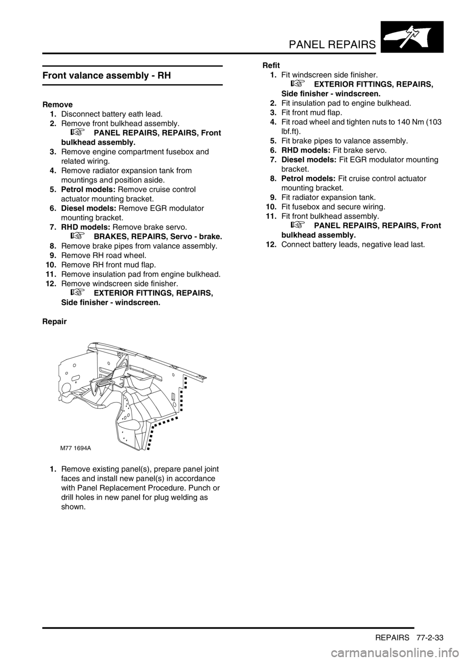
1.Remove existing panel(s), prepare panel joint
faces and install new panel(s) in accordance
with Panel Replacement Procedure. Punch or
drill holes in new panel for plug welding as
shown.Refit
1.Fit windscreen side finisher.
+ EXTERIOR FITTINGS, REPAIRS,
Side finisher - windscreen.
2.Fit insulation pad to engine bulkhead.
3.Fit front mud flap.
4.Fit road wheel and tighten nuts to 140 Nm (103
lbf.ft).
5.Fit brake pipes to valance assembly.
6. RHD models: Fit brake servo.
7. Diesel models: Fit EGR modulator mounting
bracket.
8. Petrol models: Fit cruise control actuator
mounting bracket.
9.Fit radiator expansion tank.
10.Fit fusebox and secure wiring.
11.Fit front bulkhead assembly.
+ PANEL REPAIRS, REPAIRS, Front
bulkhead assembly.
12.Connect battery leads, negative lead last.
M77 1694A
Page 1101 of 1529
PANEL REPAIRS
77-2-34 REPAIRS
Front valance assembly - LH
Remove
1.Disconnect both battery leads, negative lead
first.
2.Disconnect leads/multiplug from alternator.
3.Remove front bulkhead assembly.
+ PANEL REPAIRS, REPAIRS, Front
bulkhead assembly.
4.Remove ABS modulator unit.
+ BRAKES, REPAIRS, Modulator unit
- ABS.
5. LHD models: Remove brake servo.
+ BRAKES, REPAIRS, Servo - brake.
6.Remove brake pipes from valance assembly.
7.Remove PAS/ACE reservoir.
8. Models with A/C: Remove A/C pipes from
valance assembly.
9.Remove wiring harness from valance
assembly.
10.Remove LH front road wheel.
11.Remove LH front mud flap.
12.Remove insulation pad from engine bulkhead.
13.Remove windscreen side finisher.
+ EXTERIOR FITTINGS, REPAIRS,
Side finisher - windscreen.
Repair
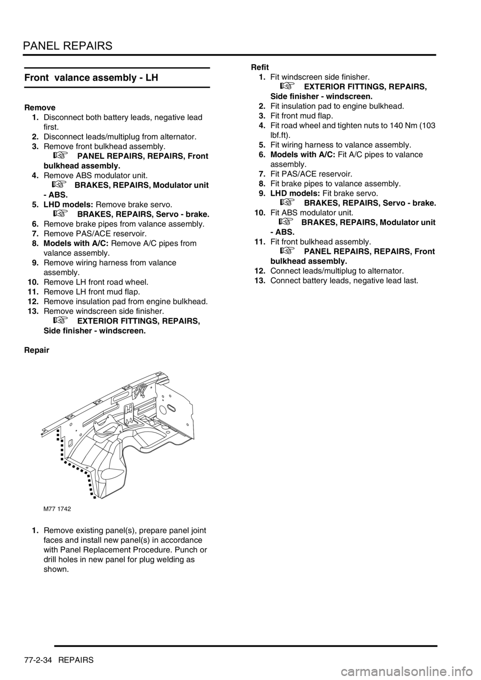
1.Remove existing panel(s), prepare panel joint
faces and install new panel(s) in accordance
with Panel Replacement Procedure. Punch or
drill holes in new panel for plug welding as
shown.Refit
1.Fit windscreen side finisher.
+ EXTERIOR FITTINGS, REPAIRS,
Side finisher - windscreen.
2.Fit insulation pad to engine bulkhead.
3.Fit front mud flap.
4.Fit road wheel and tighten nuts to 140 Nm (103
lbf.ft).
5.Fit wiring harness to valance assembly.
6. Models with A/C: Fit A/C pipes to valance
assembly.
7.Fit PAS/ACE reservoir.
8.Fit brake pipes to valance assembly.
9. LHD models: Fit brake servo.
+ BRAKES, REPAIRS, Servo - brake.
10.Fit ABS modulator unit.
+ BRAKES, REPAIRS, Modulator unit
- ABS.
11.Fit front bulkhead assembly.
+ PANEL REPAIRS, REPAIRS, Front
bulkhead assembly.
12.Connect leads/multiplug to alternator.
13.Connect battery leads, negative lead last.
M77 1742
Page 1139 of 1529

CORROSION PREVENTION AND SEALING
77-4-6 CORROSION PREVENTION
Corrosion prevention
Factory treatments
During production, vehicle bodies are treated with the following anti-corrosion materials:
lA PVC-based underbody sealer which is sprayed onto the underside of the main floor, rear floor, front and rear
wheelarches and the front valance assembly;
lAn application of cavity wax which is sprayed into the sill panels, 'A' post, 'B-C' post, fuel filler aperture, body rear
panel and the lower areas of the door panels;
lA coating of underbody wax which is applied to the entire underbody inboard of the sill vertical flanges, and
covers all moving and flexible components EXCEPT for wheels, tyres, brakes and exhaust;
lA coat of protective wax applied to the engine bay area.
Whenever body repairs are carried out, ensure the anti-corrosion materials in the affected area are repaired or
renewed as necessary using the approved materials.
+ BODY SEALING MATERIALS, MATERIALS AND APPLICATIONS, Approved materials.
Precautions during body repairs and handling
Take care when handling the vehicle in the workshop. Underbody sealers, seam sealers, underbody wax and body
panels may be damaged if the vehicle is carelessly lifted.
+ LIFTING AND TOWING, LIFTING.
Proprietary anti-corrosion treatments
The application of proprietary anti-corrosion treatments, in addition to the factory-applied treatment, could invalidate
the Corrosion Warranty and should be discouraged. This does not apply to Rover approved, compatible, preservative
waxes which may be applied on top of existing coatings.
Fitting approved accessories
When fitting accessories ensure that the vehicle's corrosion protection is not affected, either by breaking the protective
coating or by introducing a moisture trap.
Do not screw self-tapping screws directly into body panels. Fit suitable plastic inserts to the panel beforehand. Always
ensure that the edges of holes drilled into panels, chassis members and other body parts are protected with a suitable
zinc rich or acid etch primer, and follow with a protective wax coating brushed onto the surrounding area.
Do not attach painted metal surfaces of any accessory directly to the vehicle's bodywork unless suitably protected.
Where metal faces are bolted together always interpose a suitable interface material such as weldable zinc rich
primer, extruded strip, or zinc tape.
Steam cleaning and dewaxing
Due to the high temperatures generated by steam cleaning equipment, there is a risk that certain trim components
could be damaged and some adhesives and corrosion prevention materials softened or liquified.
Adjust the equipment so that the nozzle temperature does not exceed 90° C (194° F). Take care not to allow the steam
jet to dwell on one area, and keep the nozzle at least 300 mm (11.811 in) from panel surfaces.
DO NOT remove wax or lacquer from underbody or underbonnet areas during repairs. Should it be necessary to
steam clean these areas, apply a new coating of wax or underbody protection as soon as possible.
Inspections during maintenance servicing
It is a requirement of the Corrosion Warranty that the vehicle body is checked for corrosion by an authorised Land
Rover Dealer at least once a year, to ensure that the factory-applied protection remains effective.
Service Job Sheets include the following operations to check bodywork for corrosion:
lWith the vehicle on a lift, carry out visual check of underbody sealer for damage;
lWith the vehicle lowered, inspect exterior paintwork for damage and body panels for corrosion.
It will be necessary for the vehicle to be washed by the Dealer prior to inspection of bodywork if the customer has
offered the vehicle in a dirty condition.
Page 1141 of 1529
CORROSION PREVENTION AND SEALING
77-4-8 CORROSION PREVENTION
After refitting mechanical components, including hoses and pipes and other fixtures, mask off the brake discs and
apply a coat of approved underbody wax.
NOTE: Where repairs include the application of finish paint coats in the areas requiring underbody wax, carry out paint
operations before applying wax.
Cavity wax injection
Areas treated with cavity wax are shown in the previous figures. After repairs, always re-treat these areas with an
approved cavity wax. In addition, treat all interior surfaces which have been disturbed during repairs whether they
have been treated in production or not. This includes all box members, cavities and door interiors. It is permissible to
drill extra holes for access where necessary, provided these are not positioned in load-bearing members. Ensure that
such holes are treated with a suitable zinc rich primer, brushed with wax and then sealed with a rubber grommet.
Before wax injection, ensure that the cavity to be treated is free from any contamination or foreign matter. Where
necessary, clear out any debris using compressed air.
Ensure that cavity wax is applied AFTER the final paint process and BEFORE refitting any trim components.
During application, ensure that the wax covers all flange and seam areas and that it is adequately applied to all
repaired areas of both new and existing panels.
It should be noted that new panel assemblies and complete body shells are supplied without wax injection treatment.
Ensure that such treatment is carried out after repairs.
Effective cavity wax protection is vital. Always observe the following points:
lComplete all paint refinish operations before wax application;
lClean body panel areas and blow-clean cavities if necessary, before treatment;
lMaintain a temperature of 18° C (64° F) during application and drying;
lCheck the spray pattern of injection equipment;
lMask off all areas not to be wax coated and which could be contaminated by wax overspray;
lRemove body fixings, such as seat belt retractors, if contamination is at all likely;
lMove door glasses to fully closed position before treating door interiors;
lTreat body areas normally covered by trim before refitting items;
lCheck that body and door drain holes are clear after the protective wax has dried;
lKeep all equipment clean, especially wax injection nozzles.
Underbody wax
The underbody wax must be reinstated following all repairs affecting floor panels. The wax is applied over paints and
underbody sealers.
Remove old underbody wax completely from a zone extending at least 200 mm (7.874 in) beyond the area where new
underbody sealer is to be applied.
Engine bay wax
Reinstate all protective engine bay wax disturbed during repairs using an approved material.
Where repairs have involved replacement of engine bay panels, treat the entire engine compartment including all
components, clips and other fixtures with an approved underbonnet lacquer or wax.
+ BODY SEALING MATERIALS, MATERIALS AND APPLICATIONS, Approved materials.
Page 1142 of 1529
CORROSION PREVENTION AND SEALING
SEALING 77-4-9
SEALING
Body Sealing
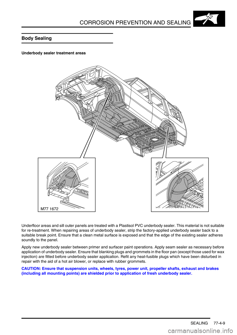
Underbody sealer treatment areas
Underfloor areas and sill outer panels are treated with a Plastisol PVC underbody sealer. This material is not suitable
for re-treatment. When repairing areas of underbody sealer, strip the factory-applied underbody sealer back to a
suitable break point. Ensure that a clean metal surface is exposed and that the edge of the existing sealer adheres
soundly to the panel.
Apply new underbody sealer between primer and surfacer paint operations. Apply seam sealer as necessary before
application of underbody sealer. Ensure that blanking plugs and grommets in the floor pan (except those used for wax
injection) are fitted before underbody sealer application. Refit any heat-fusible plugs which have been disturbed in
repair with the aid of a hot air blower, or replace with rubber grommets.
CAUTION: Ensure that suspension units, wheels, tyres, power unit, propeller shafts, exhaust and brakes
(including all mounting points) are shielded prior to application of fresh underbody sealer.
Page 1167 of 1529
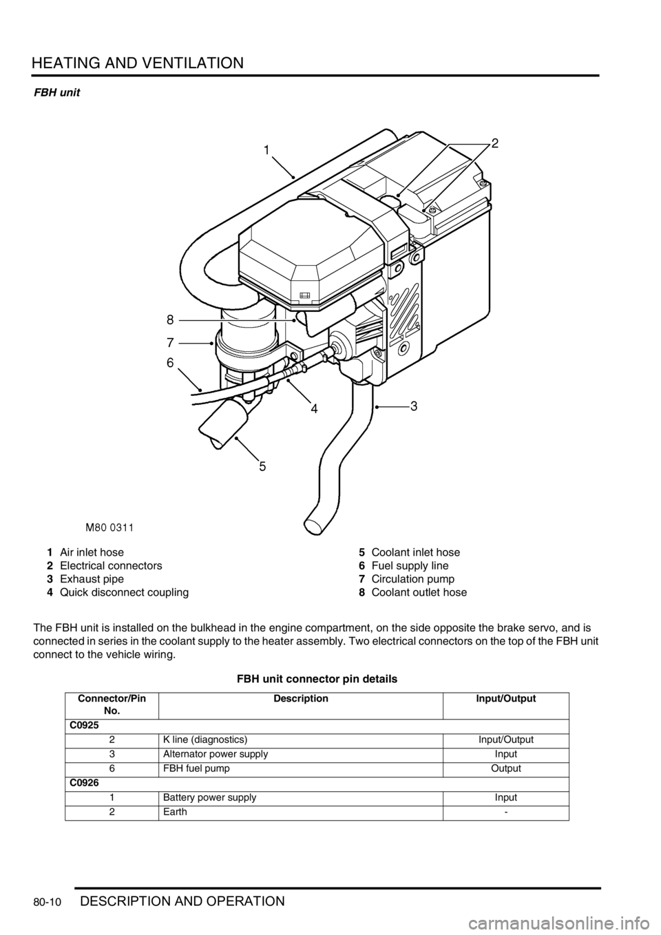
HEATING AND VENTILATION
80-10DESCRIPTION AND OPERATION
FBH unit
1Air inlet hose
2Electrical connectors
3Exhaust pipe
4Quick disconnect coupling5Coolant inlet hose
6Fuel supply line
7Circulation pump
8Coolant outlet hose
The FBH unit is installed on the bulkhead in the engine compartment, on the side opposite the brake servo, and is
connected in series in the coolant supply to the heater assembly. Two electrical connectors on the top of the FBH unit
connect to the vehicle wiring.
FBH unit connector pin details
Connector/Pin
No.Description Input/Output
C0925
2 K line (diagnostics) Input/Output
3 Alternator power supply Input
6 FBH fuel pump Output
C0926
1 Battery power supply Input
2Earth -
Page 1292 of 1529
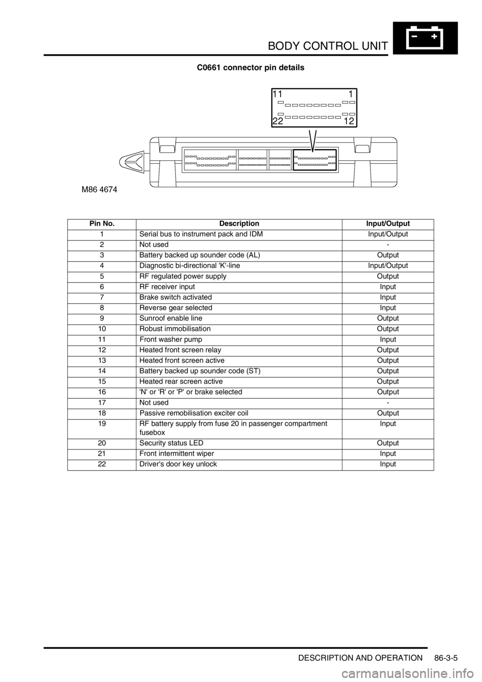
BODY CONTROL UNIT
DESCRIPTION AND OPERATION 86-3-5
C0661 connector pin details
Pin No. Description Input/Output
1 Serial bus to instrument pack and IDM Input/Output
2 Not used -
3 Battery backed up sounder code (AL) Output
4 Diagnostic bi-directional 'K'-line Input/Output
5 RF regulated power supply Output
6 RF receiver input Input
7 Brake switch activated Input
8 Reverse gear selected Input
9 Sunroof enable line Output
10 Robust immobilisation Output
11 Front washer pump Input
12 Heated front screen relay Output
13 Heated front screen active Output
14 Battery backed up sounder code (ST) Output
15 Heated rear screen active Output
16 'N' or 'R' or 'P' or brake selected Output
17 Not used -
18 Passive remobilisation exciter coil Output
19 RF battery supply from fuse 20 in passenger compartment
fuseboxInput
20 Security status LED Output
21 Front intermittent wiper Input
22 Driver's door key unlock Input
Page 1303 of 1529

BODY CONTROL UNIT
86-3-16 DESCRIPTION AND OPERATION
Cruise control
The BCU processes several signals used for cruise control:
lWhen the brake pedal is pressed, a low voltage brake lamp signal is sent via the BCU to the cruise control ECU.
lThe gear position switch sends an input via the BCU to the cruise control ECU if the selector lever is in Park,
Neutral or Reverse.
lA voltage supply is fed from the BCU to the cruise control SET+ switch.
lA voltage supply is fed from the BCU to the cruise control RES switch.
On vehicles with automatic transmission, if the BCU receives an input from the gear position switch or the brake pedal
switch, the BCU sends a signal to the cruise control ECU to cancel or inhibit cruise control operation.
+ ENGINE MANAGEMENT SYSTEM - Td5, DESCRIPTION AND OPERATION, Description.
+ ENGINE MANAGEMENT SYSTEM - V8, DESCRIPTION AND OPERATION, Description - cruise control.
Shift interlock (where fitted)
On automatic gearbox models, the BCU and IDM combine with an interlock relay located in the passenger
compartment fuse box to operate a shift interlock solenoid, so that the gear selector lever cannot be moved out of
Park until certain logical conditions have been satisfied. Operation of the interlock may be affected, if the battery
becomes discharged.
+ AUTOMATIC GEARBOX - ZF4HP22 - 24, DESCRIPTION AND OPERATION, Description.
Ignition key interlock (where fitted)
On automatic gearbox models, the ignition key interlock solenoid prevents removal of the ignition key from the ignition
switch when the transmission gear selector is not in the Park position. The logic control operation for this is performed
by the BCU.
Transfer box interlock (where fitted)
On automatic gearbox models, a transfer box interlock solenoid is controlled by the IDM to prevent transfer box shift
lever being moved out of high or low range unless certain conditions have been satisfied. The IDM controls the
operation of the transfer box relay which is located in the passenger compartment fuse box.
+ TRANSFER BOX - LT230SE, DESCRIPTION AND OPERATION, Description.
Gear position switch
A gear position switch is located on the automatic gearbox and is used to inform the BCU of the gear selector lever
position. The BCU has four sensing inputs from the gear position switch contacts W, X, Y, Z, which are used to
determine the gearbox drive status at any particular instance. The BCU gives an output corresponding to the gearbox
status derived from the gear position switch inputs. The logic states defining the gear selector positions are listed in
the table below, where Z1, Z2, Z3 and Z4 represent intermediate states which exist as the selector lever position is
changed:
Gear position Switch contacts
WX Y Z
P (Park) 1 0 0 0
Z11100
R (Reverse) 0 1 0 0
Z11100
N (Neutral) 1 1 1 0
Z21010
D (Drive) 1 0 1 1
Z31111
30111
Z40011
20001
Z40011
10010