1999 LAND ROVER DISCOVERY light
[x] Cancel search: lightPage 1317 of 1529

BODY CONTROL UNIT
86-3-30 DESCRIPTION AND OPERATION
Interior courtesy lamps
To determine when to provide an interior courtesy lamps enable output, the BCU checks the following input
conditions:
lIgnition state.
lTransit mode.
lDriver's door open.
lPassenger or rear door open.
The courtesy lamps operate at full brightness when they are first switched on. The BCU then gradually dims the lamps
(fade-out) before completely switching them off. Fade-out occurs over a period of two seconds following the logical
control signal to turn off the lights. When a door is opened, the BCU provides earth paths from the interior lamps, the
load space lamp and the ignition switch illumination. The following table lists the courtesy lamps operation and
duration for holding the lamps on that occurs after the BCU has detected a condition that signals the courtesy lamps
should be switched on:
Instrument pack
The BCU communicates with the instrument pack to provide a range of functions.
Odometer update
The BCU can be programmed for one of two options:
lOption 1 – no odometer error warning.
lOption 2 – odometer error warning.
In order to provide an LCD flash request to the instrument pack via the communications link, the following inputs are
checked:
lIgnition state.
lInstrument pack odometer value (via the communications link).
lBCU odometer value.
The function is only active when the ignition state is on. The maximum allowed value is 999,999 miles (1,608,999
km).If the instrument pack odometer value is greater than the maximum allowed value, the maximum value is
assumed. The BCU odometer value is stored in EEPROM. If 16 identical values of the instrument pack odometer
reading is received consecutively, the instrument pack odometer value is compared with the BCU odometer value. If
the consecutive readings from the instrument pack differ, the BCU odometer value is incremented accordingly. If the
BCU odometer value is less than the instrument pack odometer value by up to 10 km, the BCU odometer value is set
equal to the instrument pack odometer value.
If the odometer warning option is enabled, and the contents of the instrument pack odometer value buffer is identical
to, or greater than BCU odometer value ± 10 km, the BCU sends an LED flash request to the instrument pack.
In the event of a communications link failure, this function will be unable to operate.
Control signal Additional conditions Duration
Door open - 10 minutes
Unlock signal from remote transmitter All doors closed and ignition switch not in
position III1 minute
Unlock signal from the driver's door lock All doors closed and ignition switch not in
position III1 minute
Ignition switch turned from position II or III to
position 0All doors closed 1 minute
Door changed from open to closed All other doors closed and ignition switch not
in position III15 seconds
Ignition switch in position III - Timer cancelled
BCU receives a lock command - Timer cancelled
Vehicle has transit mode enabled - 15 seconds on all occasions
Page 1321 of 1529

BODY CONTROL UNIT
86-3-34 DESCRIPTION AND OPERATION
Key-in warning
The BCU can be programmed to one of two options:
lOption 1 – no timeout.
lOption 2 – no key-in warning.
The BCU issues an audible warning No. 2 request, depending on the status of the following inputs:
lIgnition state.
lIgnition key inserted.
lDriver's door open.
If the key-in warning is programmed into the BCU for operation, audible warning No.2 will be requested if the ignition
switch is off, the ignition key inserted signal is on and the driver's door open signal is ON.
In the event of a communications link failure occurring, the audible warning request is not sent to the instrument pack.
SLABS HDC warning
The BCU issues an audible warning No. 3 request, depending on the status of the following inputs:
lIgnition state.
lSLABS HDC warning.
The SLABS warning transmitted by the SLABS ECU is a 2 Hz signal, audible warning No. 3 is requested on every
falling edge of this signal. If the signal from the SLABS ECU stays low for more than 650 ms, audible warning No. 3
is requested every 2 seconds, for 30 seconds, while the signal stays low.
In the event of a communications link failure occurring, the audible warning request is not sent to the instrument pack.
Transfer box in neutral warning
If the transfer box is in the neutral position and the ignition switch is on, the BCU issues an audible warning No. 4
request. The BCU checks for the following inputs:
lTransfer box neutral selected.
lIgnition on.
The transfer box in neutral warning is activated by communicating with the instrument pack via the serial datalink. If
a communications link failure occurs while the transfer box in neutral warning is active, the audible warning will not
operate.
Lights on warning
If the ignition switch is off while the side lamps or headlamps on and the driver's door is opened, the BCU issues an
audible warning No. 5 request.
The BCU checks for the following inputs:
lDriver's door open.
lIgnition on.
lSide lamps.
lDipped beam state.
lMain beam state.
The lights on warning is activated by communicating with the instrument pack via the serial datalink. If a
communications link failure occurs while the lights on warning is active, the audible warning will not operate.
SLABS raise/lower
Before enabling a SLS vehicle raise/ lower request, the BCU checks the logical condition of the following inputs:
lIgnition state.
lSLABS raise request.
lSLABS lower request.
If the ignition switch is in position 0 or I, the vehicle raise/ lower request is off.
With the ignition switch in position II, and the 'SLABS raise' request and 'SLABS lower' request both off, the vehicle
raise/ lower request output is driven at 25 Hz with a 50% duty cycle and the vehicle height remains unchanged.
If the 'SLABS lower' request input is on, the vehicle raise/lower request output is driven at 25 Hz with a 25% duty cycle,
lowering the vehicle.
If the 'SLABS raise' request input is on, the vehicle raise/lower request output is driven at a 25 Hz with a 75% duty
cycle.
Page 1339 of 1529

ALARM SYSTEM AND HORN
86-4-16 DESCRIPTION AND OPERATION
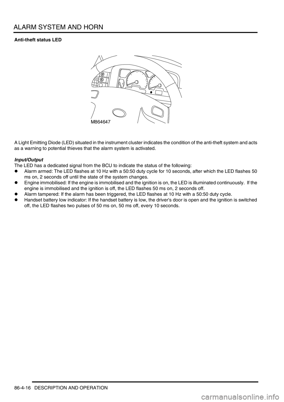
Anti-theft status LED
A Light Emitting Diode (LED) situated in the instrument cluster indicates the condition of the anti-theft system and acts
as a warning to potential thieves that the alarm system is activated.
Input/Output
The LED has a dedicated signal from the BCU to indicate the status of the following:
lAlarm armed: The LED flashes at 10 Hz with a 50:50 duty cycle for 10 seconds, after which the LED flashes 50
ms on, 2 seconds off until the state of the system changes.
lEngine immobilised: If the engine is immobilised and the ignition is on, the LED is illuminated continuously. If the
engine is immobilised and the ignition is off, the LED flashes 50 ms on, 2 seconds off.
lAlarm tampered: If the alarm has been triggered, the LED flashes at 10 Hz with a 50:50 duty cycle.
lHandset battery low indicator: If the handset battery is low, the driver's door is open and the ignition is switched
off, the LED flashes two pulses of 50 ms on, 50 ms off, every 10 seconds.
Page 1340 of 1529

ALARM SYSTEM AND HORN
DESCRIPTION AND OPERATION 86-4-17
Operation
Standard system functions
All vehicles have the following functions as standard.
lLocking.
lUnlocking.
lFuel cut off switch unlocking.
lInternal locking.
lElectric fuel flap release.
Locking
The doors are locked by pressing the lock button on the handset or by locking the vehicle from the driver's door with
the key.
In order to lock the vehicle, the following conditions must be met:
lThe driver's door is closed.
lThe ignition is off.
lThe fuel cut off switch is not tripped.
lThe bonnet is closed.
lThe vehicle is not super locked.
Depending on system configuration a mislock occurs if these conditions are not met. The doors may lock (depending
on condition not met) and the system may not fully arm, depending on configuration of the system. If a mislock occurs
an audible warning is emitted and the vehicle becomes partially armed.
Unlocking
The doors are unlocked by pressing the unlock button on the handset or by unlocking the vehicle from the driver's
door with the key. This may unlock only the driver's door or it may unlock all doors depending on system configuration.
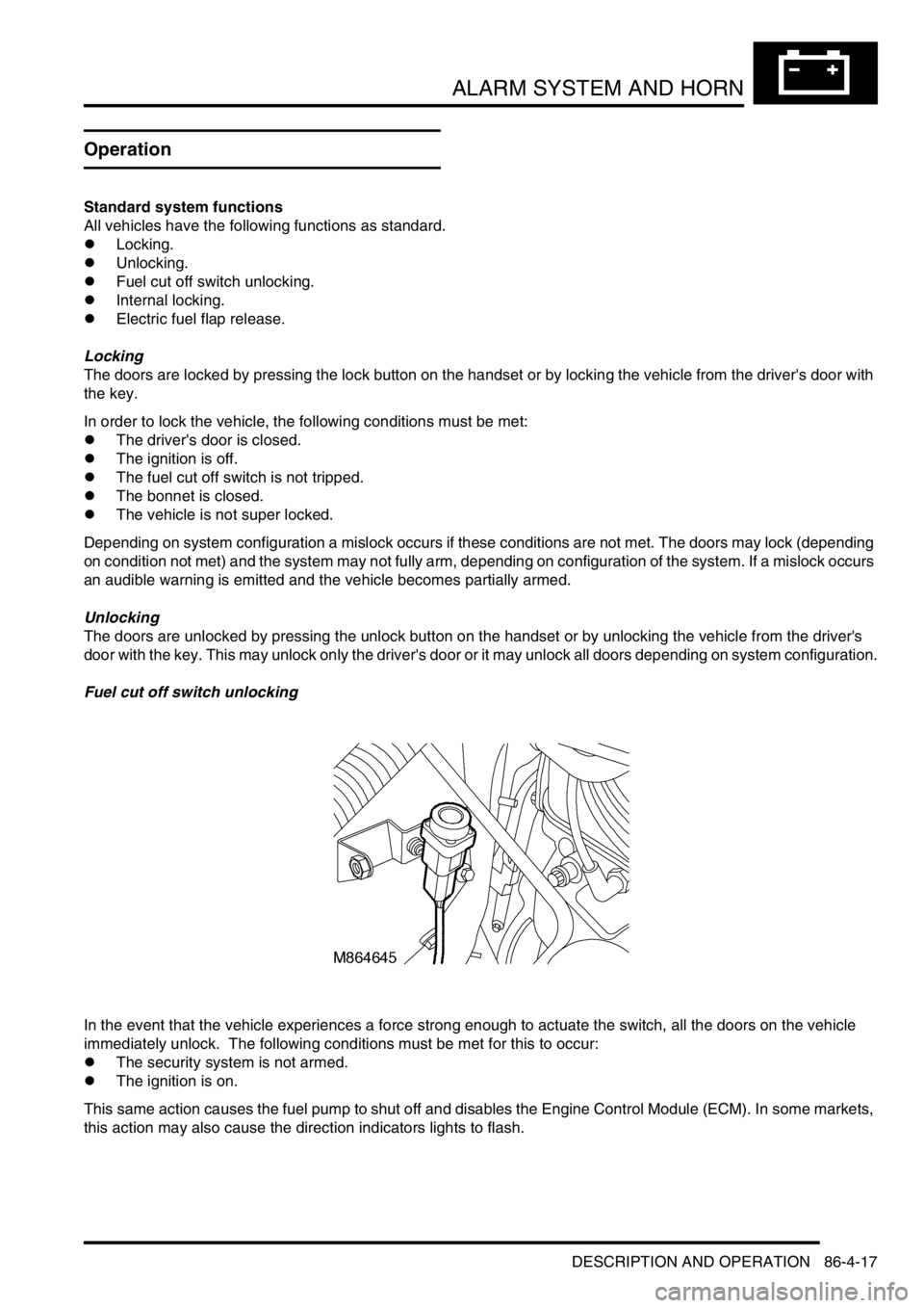
Fuel cut off switch unlocking
In the event that the vehicle experiences a force strong enough to actuate the switch, all the doors on the vehicle
immediately unlock. The following conditions must be met for this to occur:
lThe security system is not armed.
lThe ignition is on.
This same action causes the fuel pump to shut off and disables the Engine Control Module (ECM). In some markets,
this action may also cause the direction indicators lights to flash.
Page 1351 of 1529

ALARM SYSTEM AND HORN
86-4-28 REPAIR
Receiver - alarm system - models with
sunroof
$% 86.77.31
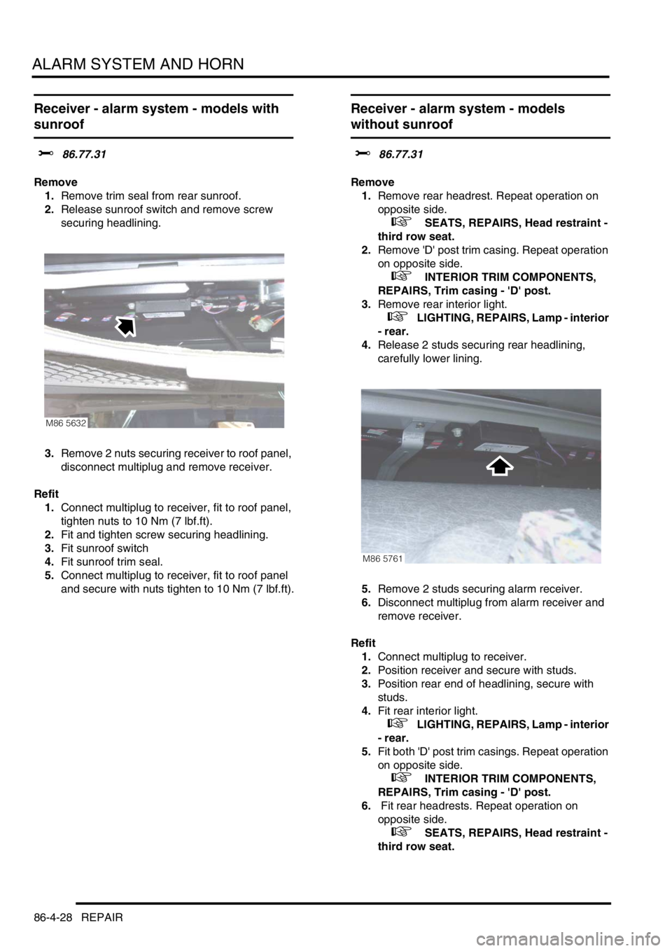
Remove
1.Remove trim seal from rear sunroof.
2.Release sunroof switch and remove screw
securing headlining.
3.Remove 2 nuts securing receiver to roof panel,
disconnect multiplug and remove receiver.
Refit
1.Connect multiplug to receiver, fit to roof panel,
tighten nuts to 10 Nm (7 lbf.ft).
2.Fit and tighten screw securing headlining.
3.Fit sunroof switch
4.Fit sunroof trim seal.
5.Connect multiplug to receiver, fit to roof panel
and secure with nuts tighten to 10 Nm (7 lbf.ft).
Receiver - alarm system - models
without sunroof
$% 86.77.31
Remove
1.Remove rear headrest. Repeat operation on
opposite side.
+ SEATS, REPAIRS, Head restraint -
third row seat.
2.Remove 'D' post trim casing. Repeat operation
on opposite side.
+ INTERIOR TRIM COMPONENTS,
REPAIRS, Trim casing - 'D' post.
3.Remove rear interior light.
+ LIGHTING, REPAIRS, Lamp - interior
- rear.
4.Release 2 studs securing rear headlining,
carefully lower lining.
5.Remove 2 studs securing alarm receiver.
6.Disconnect multiplug from alarm receiver and
remove receiver.
Refit
1.Connect multiplug to receiver.
2.Position receiver and secure with studs.
3.Position rear end of headlining, secure with
studs.
4.Fit rear interior light.
+ LIGHTING, REPAIRS, Lamp - interior
- rear.
5.Fit both 'D' post trim casings. Repeat operation
on opposite side.
+ INTERIOR TRIM COMPONENTS,
REPAIRS, Trim casing - 'D' post.
6. Fit rear headrests. Repeat operation on
opposite side.
+ SEATS, REPAIRS, Head restraint -
third row seat.
M86 5632
M86 5761
Page 1377 of 1529

IN CAR ENTERTAINMENT
86-6-10 DESCRIPTION AND OPERATION
Aerial
On base and midline ICE systems an AM/FM aerial is built-in to the side window glass on the RH side of the vehicle.
An amplifier is located on the frame above the rear side widow behind the rear quarter trim, and is secured (and
earthed) with one bolt. Coaxial leads connect the aerial to the aerial amplifier and radio cassette. Power is supplied
from the auxilary relay in the engine compartment fuse box, through a fuse in the passenger compartment fusebox to
the amplifier.
On high line ICE systems two amplified aerials are built-in to the side window glass of the vehicle. The two aerials are
an AM/FM aerial on the RH side, and an FM aerial on the LH side. The amplifier for each aerial are located on the
frame above each rear side widow behind the rear quarter trim, and are each secured (and earthed) with one bolt.
Amplified aerials improve the reception quality, the FM aerial gives improved reception in areas of poor signal
(diversity) conditions in urban areas. A Power feed from the radio cassette player is connected to the amplified aerials,
power is available when the cassette player is operating. The aerials are connected to the radio cassette player by
two coaxial cables, a small plug connects the FM only aerial, a larger plug connects the AM/FM aerial.
Power amplifier (high line system)
The amplifier is located on a bracket under the LH front seat and is secured with three screws and washers. The
amplifier receives inputs from the radio, radio cassette player or (via the radio cassette player) the CD-autochanger.
Power for the amplifier is supplied from the passenger compartment fuse box. The amplifier will power up when an
enable logic signal is sent from the radio cassette, this signal is sent by the radio cassette when it is turned on.
CD-autochanger (high line system)
A CD-autochanger is located under the RH front seat, the unit is secured to brackets in the floor with four screws and
washers. A tray is used to hold each compact disk (CD), the loaded tray is then inserted in a magazine, the magazine
holds six trays and is then inserted into the CD-autochanger. A sliding cover protects the internal components of the
CD-autochanger from dirt entry through the magazine opening. An eject button located on the front of the CD-
autochanger can be used to release the magazine from the CD-autochanger. The sliding cover has to be opened
manually before the magazine eject button is pressed. The operation of the CD-autochanger is controlled by inputs
from the radio cassette, the control inputs can be from the radio cassette buttons, the remote radio controls or the rear
radio headphone amplifiers if they are fitted. The output from the CD-autochanger are connected to the radio cassette
player. The radio cassette player sends the outputs to the power amplifier. Power is supplied to the CD-autochanger
by a feed from the radio cassette player.
Radio headphone amplifiers (high line system)
The rear mounted radio headphone amplifiers are located in the lower rear quarter trim casing and are held in position
by a clip on the side of the headphone amplifier. Mode and function buttons are located on a control panel, the mode
button allows each of the rear seat passengers to independently select from the radio, tape or CD-autochanger. The
driver and the rear seat passengers can each listen to any of the audio devices they select. However the radio
cassette setting has overall priority e.g:
lIf the radio cassette is using a radio wave band (AM or FM), the headphone user will be able to select the cassette
tracks or CD-autochanger. The user will be able to listen to same radio band that is selected on the radio
cassette, but will not be able to change the station selected.
lIf the radio cassette has CD-autochanger selected, the headphone amplifiers will allow listening to the compact
disk but will not allow track changes. The headphone user will be able to select on all of the radio bands or
cassette tracks.
lIf the radio cassette has tape selected, the headphone amplifiers will allow listening to the tape but will not allow
track changes. The headphone user will be able to select all radio bands or CD's on the CD-autochanger.
If one headphone amplifier unit has control of the tape player, CD or radio, the other headphone amplifier will be able
to listen and be able to change tape tracks or radio bands. Other buttons allow a search seek function of radio band
or compact disk track, reversal of the tape, radio station and volume adjustment depending on the current operating
mode. If one radio headphone amplifier has control of the radio, tape or CD autochanger the other radio headphone
amplifier is able to change the track or radio band selected. A headphone socket with a glow ring is located on the
control panel. When a headphone is turned on , a 'headphone-module active' signal is sent to the radio cassette
player. The design incorporates panel illumination and a glow-ring to locate the socket in low light conditions. To
control the audio output from the radio headphone amplifiers, signals are sent to and received from the radio cassette
player.
Page 1385 of 1529

IN CAR ENTERTAINMENT
86-6-18 DESCRIPTION AND OPERATION
The console unit has three buttons which allow for minimum operation of the unit without using the handset:
lThe Stop/Eject button stops playback when pressed – 'Stop' appears on the LCD monitor as confirmation.
When the playback is stopped, a further press of the Stop/Eject button ejects the DVD or CD from the DVD
console – 'Eject' appears on the LCD monitor as confirmation.
lThe Play/Pause button begins play of the DVD or CD when pressed – 'Play' appears on the LCD monitor as
confirmation.
During play, pressing the Play/Pause button temporarily pauses the play – 'Pause' appears on the LCD monitor
as confirmation. A second press of the Play/Pause button resumes the play.
lThe Speaker button switches the DVD or CD audio to play through the vehicle audio speakers system. When the
CD is selected on the ICE head unit in the fascia, pressing the button allows the DVD or CD audio to play through
the vehicle audio speakers – 'Speaker On' appears on the LCD monitor. A second press of the button prevents
the DVD or CD audio playing through the vehicle audio speakers – 'Speaker Off' appears on the LCD monitor.
NOTE: These functions are also available from buttons on the remote handset.
Two sockets are provided on the left hand side of the unit and one socket on the right hand side of the unit for the use
of headphones with the overhead console unit. This allows the three occupants of the 2nd row seats to listen to the
DVD output using headphones. Occupants of the 3rd row seats can also listen to the DVD output using headphones
connected into the two radio/headphone amplifier units.
The console has three Phono sockets which allow for the use of an auxiliary video unit or video games console to be
connected to the system and use the LCD monitor for display. The sockets are colour coded for correct auxiliary input
connection as follows:
lRED – Right channel audio input
lWHITE – Left channel audio input
lYELLOW – Video input.
A slot is provided on the right hand side of the console for insertion of a DVD or CD into the console unit. The DVD
or CD can be inserted into the slot with the label side facing upwards. The DVD or CD is ejected from the slot when
the Stop/Eject button is pressed.
When the LCD monitor is in the lowered position, an infra-red receiver is exposed and receives transmitted signals
from the remote control handset. The receiver is located adjacent to the status LED which is illuminated when the
system is active.
The DVD player in the overhead console has an auto eject feature to protect the DVD or CD in the unit from damage
due to excessive heat. The status LED will flash to alert the user to this condition. If the temperature exceeds 70°C
(158°F), the DVD system automatically ejects the DVD or CD and shuts down, preventing further operation. When
the temperature in the vehicle has returned to 64°C (147°F) or less, press the 'Power' button on the handset or open
the LCD monitor to switch on the system.
Liquid Crystal Display (LCD) Monitor
The LCD monitor is suited for use with the in-car DVD system because of its compact, lightweight design and low
power consumption. The LCD monitor is a highly sophisticated unit and should be treated with care. Observe the
following precautions when using or handling the LCD monitor.
lDo not press on the monitor, this can distort the picture and cause permanent damage to the LCD panel.
lClean the LCD panel with a damp soft cloth with a mild household detergent if necessary. DO NOT use solvents,
commercial cleaners or anti-static sprays.
lDo not use the LCD in temperatures below 0°C (32°F) or above 80°C (176°F). If the vehicle is used in a cold
climate or in direct sunlight in a warm climate, the LCD monitor may not function correctly outside of the
temperatures stated. The picture may not be clear. This will not cause permanent damage to the monitor and the
picture should return to normal once the temperature is within the operating range as stated.
Page 1387 of 1529

IN CAR ENTERTAINMENT
86-6-20 DESCRIPTION AND OPERATION
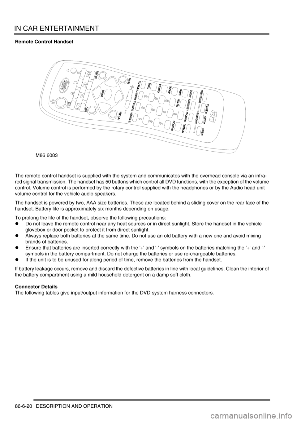
Remote Control Handset
The remote control handset is supplied with the system and communicates with the overhead console via an infra-
red signal transmission. The handset has 50 buttons which control all DVD functions, with the exception of the volume
control. Volume control is performed by the rotary control supplied with the headphones or by the Audio head unit
volume control for the vehicle audio speakers.
The handset is powered by two, AAA size batteries. These are located behind a sliding cover on the rear face of the
handset. Battery life is approximately six months depending on usage.
To prolong the life of the handset, observe the following precautions:
lDo not leave the remote control near any heat sources or in direct sunlight. Store the handset in the vehicle
glovebox or door pocket to protect it from direct sunlight.
lAlways replace both batteries at the same time. Do not use an old battery with a new one and avoid mixing
brands of batteries.
lEnsure that batteries are inserted correctly with the '+' and '-' symbols on the batteries matching the '+' and '-'
symbols in the battery compartment. Do not charge the batteries or use re-chargeable batteries.
lIf the unit is to be unused for along period of time, remove the batteries from the handset.
If battery leakage occurs, remove and discard the defective batteries in line with local guidelines. Clean the interior of
the battery compartment using a mild household detergent on a damp soft cloth.
Connector Details
The following tables give input/output information for the DVD system harness connectors.