Page 567 of 1529

TRANSFER BOX - LT230SE
41-42 REPAIRS
Switch - high low - warning
$% 41.30.05
Remove
1.Raise vehicle on a ramp.
2.Release switch multiplug from bracket on
transfer box and disconnect from harness.
3.Remove switch from transfer box and discard
sealing washer.
Refit
1.Ensure sealing washer, switch thread and
mating face on transfer box is clean.
2.Fit sealing washer to switch, fit and tighten
switch to transfer box to 25 Nm (18 lbf.ft) .
3.Connect multiplug to harness and fit multiplug
to bracket on transfer box.
4.Lower vehicle.
Switch(es) - differential lock warning
From 03 MY
$% 41.30.06
Remove
1.Remove front propeller shaft.
+ PROPELLER SHAFTS, REPAIRS,
Propeller shaft - front.
2.Release and disconnect both differential lock
warning switch multiplugs.
3.Remove differential lock front warning switch,
remove and discard sealing washer.
4.Remove differential lock rear warning switch,
remove and discard sealing washer.
Refit
1.Clean switches and mating face on transfer
gearbox.
2.Apply sealant, STC 50552 to switch threads.
3.Use new sealing washers, fit and tighten
differential lock warning switches to 26 Nm (19
lbf.ft)
4.Connect and secure both switch multiplugs.
5.Fit front propeller shaft.
+ PROPELLER SHAFTS, REPAIRS,
Propeller shaft - front.
Page 582 of 1529
TRANSFER BOX - LT230SE
OVERHAUL 41-57
Refit
1.Clean differential components. Remove all
traces of sealant from housings and bolts,
differential lock warning lamp switches and
detent plugs.
2.Lubricate components with gearbox oil.
3.Position differential in soft jawed vice and fit
front bearing using tool LRT-41-008. 4.Invert differential in soft jawed vice, and fit low
range gear with dog teeth facing uppermost.
5.Fit high/low hub ensuring that machined
groove on hub teeth faces towards low range
gear.
6.Fit high/low selector sleeve ensuring that
alignment marks on hub and sleeve are
together.
7.Fit bush to high range gear ensuring collar is
uppermost.
8.Fit high range gear and bush onto shaft.
9.Fit new rear bearing using tool LRT-41-008.
Page 590 of 1529

TRANSFER BOX - LT230SE
OVERHAUL 41-65
9. 03 Model Year onwards:Note position of
longest bolt and remove 8 bolts securing front
output shaft housing to main casing; remove
housing.
10. 03 Model Year onwards:Remove 3 bolts
securing differential lock selector housing and
bracket, remove housing.
11. 03 Model Year onwards:Remove and discard
'O' rings from selector housing.
12. 03 Model Year onwards:Remove differential
lock detent plug, recover spring and ball.
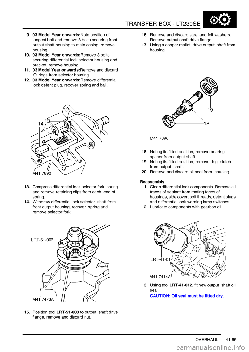
13.Compress differential lock selector fork spring
and remove retaining clips from each end of
spring.
14.Withdraw differential lock selector shaft from
front output housing, recover spring and
remove selector fork.
15.Position tool LRT-51-003 to output shaft drive
flange, remove and discard nut. 16.Remove and discard steel and felt washers.
Remove output shaft drive flange.
17.Using a copper mallet, drive output shaft from
housing.
18.Noting its fitted position, remove bearing
spacer from output shaft.
19.Noting its fitted position, remove dog clutch
from output shaft.
20.Remove and discard oil seal from housing.
Reassembly
1.Clean differential lock components. Remove all
traces of sealant from mating faces of
housings, side cover, bolt threads, detent plugs
and differential lock warning lamp switches.
2.Lubricate components with gearbox oil.
3.Using tool LRT-41-012, fit new output shaft oil
seal.
CAUTION: Oil seal must be fitted dry.
Page 596 of 1529
TRANSFER BOX - LT230SE
OVERHAUL 41-71
7.Remove high range gear and bush.
8.Make suitable alignment marks between high/
low selector sleeve and hub, remove selector
sleeve. 9.Using a suitable press and thrust button LRT-
41-001remove high/low hub and low range
gear.
Reassembly
1.Clean differential components.
2.Lubricate components with gearbox oil.
3.Fit differential in soft jawed vice, and fit low
range gear with dog teeth facing uppermost.
4.Fit high/low hub ensuring that machined
groove on hub teeth faces towards low range
gear.
5.Fit high/low selector sleeve ensuring that
alignment marks on hub and sleeve are
together.
6.Fit bush to high range gear ensuring collar is
uppermost.
7.Fit high range gear and bush onto shaft.
Page 598 of 1529
AUTOMATIC GEARBOX - ZF4HP22 - 24
DESCRIPTION AND OPERATION 44-1
AUTOMATIC GE ARBOX - ZF4HP22 - 24 DESCRIPTION AND OPERAT ION
Automatic gearbox component layout
1Selector lever assembly
2Gearbox
3Electronic automatic transmission ECU
4Selector position switch5Oil cooler
6Fluid lines
7Breather tube
8Selector cable
Page 599 of 1529
AUTOMATIC GEARBOX - ZF4HP22 - 24
44-2 DESCRIPTION AND OPERATION
Control schematic
Page 600 of 1529
AUTOMATIC GEARBOX - ZF4HP22 - 24
DESCRIPTION AND OPERATION 44-3
1Transmission high/low switch
2Mode switch
3Gear position switch connector
4Solenoid valve/speed sensor connector
5Electronic automatic transmission ECU
6Engine control module
7Diagnostic socket
8Instrument pack
9Transmission fluid temperature sensor
10Body control unit
11Battery power supply
12Ignition power supply
Page 601 of 1529

AUTOMATIC GEARBOX - ZF4HP22 - 24
44-4 DESCRIPTION AND OPERATION
Description
General
The automatic gearbox is a four speed unit with electronic control of gear selection, shift quality and torque converter
lock-up. Selections on the selector lever assembly are transmitted to the gearbox by a selector cable. A gear position
switch on the gearbox transmits the gear selection to an Electronic Automatic Transmission (EAT) ECU, which
outputs the appropriate control signals to an electro-hydraulic valve block in the gearbox. A mode switch enables the
driver to change the control mode of the EAT ECU. The EAT ECU operates warning lamps in the instrument pack to
indicate the control mode and system status.
The gearbox features a pressure lubrication system and is cooled by pumping the lubricant through an oil cooler.
On NAS market vehicles from 03 model year, the ZF 4HP24 transmission unit is introduced for use with the 4.6 litre
V8 engine. This transmission is required to accomodate the increased power output of the larger engine. The ZF
4HP22 transmission remains in use on vehicles with Td5 and 4.0 litre V8 engines.
Both transmission units are of similar construction, with the ZF 4HP24 unit being 15 mm longer than the 4HP22 unit
to accomodate a larger fluid pump. The operation of both transmission units is the same.