1999 LAND ROVER DISCOVERY differential
[x] Cancel search: differentialPage 837 of 1529

REAR SUSPENSION
64-28 REPAIRS
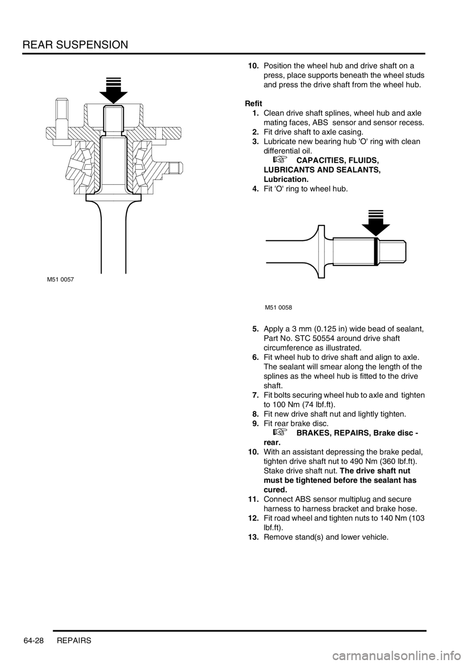
10.Position the wheel hub and drive shaft on a
press, place supports beneath the wheel studs
and press the drive shaft from the wheel hub.
Refit
1.Clean drive shaft splines, wheel hub and axle
mating faces, ABS sensor and sensor recess.
2.Fit drive shaft to axle casing.
3.Lubricate new bearing hub 'O' ring with clean
differential oil.
+ CAPACITIES, FLUIDS,
LUBRICANTS AND SEALANTS,
Lubrication.
4.Fit 'O' ring to wheel hub.
5.Apply a 3 mm (0.125 in) wide bead of sealant,
Part No. STC 50554 around drive shaft
circumference as illustrated.
6.Fit wheel hub to drive shaft and align to axle.
The sealant will smear along the length of the
splines as the wheel hub is fitted to the drive
shaft.
7.Fit bolts securing wheel hub to axle and tighten
to 100 Nm (74 lbf.ft).
8.Fit new drive shaft nut and lightly tighten.
9.Fit rear brake disc.
+ BRAKES, REPAIRS, Brake disc -
rear.
10.With an assistant depressing the brake pedal,
tighten drive shaft nut to 490 Nm (360 lbf.ft).
Stake drive shaft nut. The drive shaft nut
must be tightened before the sealant has
cured.
11.Connect ABS sensor multiplug and secure
harness to harness bracket and brake hose.
12.Fit road wheel and tighten nuts to 140 Nm (103
lbf.ft).
13.Remove stand(s) and lower vehicle.
M51 0057
M51 0058
Page 856 of 1529

BRAKES
DESCRIPTION AND OPERATION 70-3
1ABS sensor
2ABS modulator
3Return pump relay
4SLABS ECU
5Brake lamp relay
6Centre high mounted stop lamp
7LH brake lamp
8RH brake lamp
9Instrument pack10Body control unit
11Reverse lamp switch (manual gearbox)
12Diagnostic socket
13HDC switch
14Transmission high/low switch
15Centre differential lock switch
16Engine control module
17Battery power supply
18Ignition power supply
Page 861 of 1529

BRAKES
70-8 DESCRIPTION AND OPERATION
Brakes on
When the brake pedal is pressed, the input push rod and the piston initially move forward in the valve body. The valve
body and output rod then move with the input rod, against resistance from the return spring, to transmit the brake
pedal force to the master cylinder assembly.
During the initial movement of the piston, the valve, assisted by the valve spring, moves with the piston and closes
the vacuum port to isolate the chambers at the rear of the diaphragms from the vacuum source. Further movement
of the input push rod causes the piston to move away from the valve and open the air inlet port. This allows a restricted
flow of filtered ambient air through the air inlet port, which creates a servo pressure in the chambers at the rear of the
diaphragms. Force from the resultant pressure differential across the diaphragms is transmitted through the valve
body to the output push rod, augmenting the pressure being applied by the brake pedal. The force produced by the
diaphragms, in proportion to the input force, i.e. the boost ratio, is 5.6 : 1. The boost ratio remains constant, as the
input force from the brake pedal increases, until the limit of assistance is reached when servo pressure is equal to
ambient pressure.
Brakes held on
When the brake pedal effort is constant, opposing pressures cause the reaction disc to extrude onto the ratio disc,
which moves the piston against the valve to close the air inlet port. This prevents any further increase in servo
pressure and maintains a constant output force to the master cylinder assembly.
Brakes released
When the brake pedal is released, the input rod spring moves the input rod and piston rearwards within the valve body
to close the air inlet port and open the vacuum port. The air from the chambers at the rear of the diaphragms is then
evacuated, through the vacuum port and the chambers at the front of the diaphragms, to restore a partial vacuum in
all four chambers. Simultaneously, the return spring moves the valve body, diaphragms, output rod and input rod
rearwards to return them to their brakes off position.
Page 871 of 1529

BRAKES
70-18 DESCRIPTION AND OPERATION
The SLABS ECU continually calculates vehicle speed using the wheel speed inputs from all four ABS sensors. The
calculated vehicle speed is then used as a reference against which individual wheel speeds are monitored for
unacceptable acceleration or deceleration. The ABS sensor inputs are also used by the SLABS ECU to detect vehicle
deceleration rate, vehicle cornering rate and rough terrain.
The engaged forward gear and (on manual gearbox models) the clutch status are computed from the engine data
input, the engine speed input and vehicle speed. Reverse gear status is provided by an input from the reverse lamp
switch (manual gearbox models) or the BCU (automatic gearbox models). On automatic models, the BCU also
provides the neutral selected input.
In addition to controlling the brake related functions, the SLABS ECU:
lControls the operation of the self levelling suspension (SLS) system (where fitted).
+ REAR SUSPENSION, DESCRIPTION AND OPERATION, Description.
lOn V8 models, outputs a rough road signal to the ECM when traversing rough terrain.
lOutputs a vehicle speed signal.
The vehicle speed signal is output to the following systems (where fitted):
lActive Cornering Enhancement.
+ FRONT SUSPENSION, DESCRIPTION AND OPERATION, Description - ACE.
lAir conditioning.
+ AIR CONDITIONING, DESCRIPTION AND OPERATION, Description.
lCruise control.
+ ENGINE MANAGEMENT SYSTEM - Td5, DESCRIPTION AND OPERATION, Description.
+ ENGINE MANAGEMENT SYSTEM - V8, DESCRIPTION AND OPERATION, Description - engine
management.
lEngine management.
+ ENGINE MANAGEMENT SYSTEM - Td5, DESCRIPTION AND OPERATION, Description.
+ ENGINE MANAGEMENT SYSTEM - V8, DESCRIPTION AND OPERATION, Description - engine
management.
lIn-car entertainment.
+ IN CAR ENTERTAINMENT, DESCRIPTION AND OPERATION, Description.
lInstrument pack.
+ INSTRUMENTS, DESCRIPTION AND OPERATION, Description.
5 Front right inlet solenoid valve Output
6 Shuttle valve switches Input
7 Rear left outlet solenoid valve Output
8 Rear left inlet solenoid valve Output
9 Centre differential lock switch Input
10 Rear right outlet solenoid valve Output
11 Rear right inlet solenoid valve Output
12 Brake lamp relay Output
15 Return pump relay Output
C0655
7 Audible warning Output
10 Engine speed Input
Connector and pins not listed are either not used or used by the self levelling suspension system.
+ REAR SUSPENSION, DESCRIPTION AND OPERATION, Description.
Connector/Pin
No.Description Input/Output
Page 874 of 1529

BRAKES
DESCRIPTION AND OPERATION 70-21
ETC
The ETC function uses brake intervention to prevent wheel spin and maintain even torque distribution to the wheels.
ETC is automatically enabled while the brakes are off at speeds up to 62.5 mph (100 km/h), and operates the brakes
either individually or in axle pairs:
lAt speeds up to 31.3 mph (50 km/h), ETC uses individual brake intervention to maintain even torque distribution
between wheels on the same axle.
lVehicles up to 03 model year – At speeds between 0 and 62.5 mph (0 and 100 km/h), ETC also uses brake
intervention in axle pairs to maintain even torque distribution between the front and rear axles. In effect, this mode
of operation replaces the centre differential lock of the transfer box which, although still incorporated, is non
operational under normal driving conditions.
+ TRANSFER BOX - LT230SE, DESCRIPTION AND OPERATION, Description. If the centre differential
lock is in the locked condition, the SLABS ECU illuminates the ABS and ETC warning lamps and inhibits the ETC
function (the ABS, EBD and HDC functions are retained, but at degraded performance levels).
lVehicles from 03 model year (with differential lock fitted) – At speeds between 0 and 62.5 mph (0 and 100
km/h), ETC uses brake intervention in axle pairs to maintain even torque distribution between the front and rear
axles. If the centre differential lock is in the locked condition, the differential lock warning lamp in the instrument
pack is illuminated. The ABS, EBD, ETC and HDC functions are retained, but with revised parameters to suit the
locked differential.
While the ETC function is enabled, if the SLABS ECU detects a wheel accelerating faster than the average, indicating
loss of traction, it operates the ABS modulator in the active braking mode. Depending on the vehicle speed, active
braking is employed for either the brake of the affected wheel or for both brakes on the affected axle, until all four
wheels are driven at approximately the same speed again. During active braking the SLABS ECU also illuminates the
ETC warning lamp, for a minimum of 2 seconds or for the duration that ETC is active. ETC operation is desensitised
during 'hard' cornering.
HDC
HDC uses brake intervention to provide a controlled descent ability in off road conditions when engine braking is
insufficient to maintain a comfortable speed. This allows the driver to leave HDC selected and to control the vehicle's
descent speed, down to the system's minimum target speed, using only the accelerator pedal. The HDC function is
selected on/off by a switch on the fascia. When selected on, HDC is enabled in all forward gears and reverse provided:
lVehicle speed is below 31.3 mph (50 km/h).
lThe transfer box is in low range.
lOn manual gearbox vehicles, the clutch is engaged.
When HDC is enabled, the HDC information warning lamp illuminates. If HDC is selected outside the above
conditions, the HDC information warning lamp flashes and the audible warning sounds continuously.
When HDC is enabled, the SLABS ECU calculates a target speed from the throttle position element of the engine data
input, and compares this with actual speed. If the actual speed is higher than the target speed, the SLABS ECU
operates the ABS modulator in the active braking mode to slow the vehicle down to the target speed. While the braking
force is being applied, the SLABS ECU also energizes the brake lamp relay to put the brake lamps on. Active braking
is discontinued while vehicle speed is below the target speed or if the foot brakes are applied. Applying the foot brakes
during active braking may result in a pulse through the brake pedal, which is normal.
During active braking, the brakes are operated predominantly on the wheels of the leading axle, but if that is not
sufficient to achieve the required deceleration the brakes of the trailing axle are also applied. The deceleration rate is
dependent on the speed differential between initial vehicle speed and the target speed. The deceleration rates are
relatively low at higher speed differentials, then progressively increase as vehicle speed approaches the target speed.
Anti-lock braking is also enabled during active braking, but at very low speeds some wheel lock can occur.
The target speed increases as the accelerator pedal is pressed, from a programmed minimum with the accelerator
pedal released, up to a maximum of 31.3 mph (50 km/h). For any given accelerator pedal position, while travelling
uphill or on level ground the target speed is always greater than the corresponding vehicle speed, which allows the
vehicle to be driven normally without HDC intervention. However, when travelling downhill, the gravitational effect on
the vehicle means that for any given accelerator pedal position the target speed is less than the corresponding vehicle
speed, and HDC intervenes to limit vehicle speed to the target speed.
Page 1165 of 1529

HEATING AND VENTILATION
80-8DESCRIPTION AND OPERATION
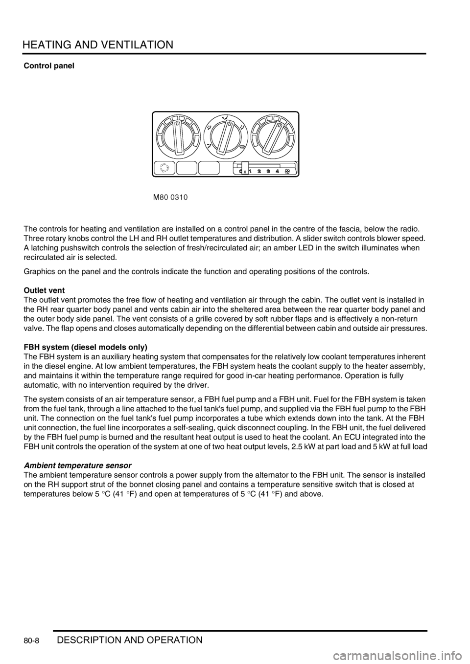
Control panel
The controls for heating and ventilation are installed on a control panel in the centre of the fascia, below the radio.
Three rotary knobs control the LH and RH outlet temperatures and distribution. A slider switch controls blower speed.
A latching pushswitch controls the selection of fresh/recirculated air; an amber LED in the switch illuminates when
recirculated air is selected.
Graphics on the panel and the controls indicate the function and operating positions of the controls.
Outlet vent
The outlet vent promotes the free flow of heating and ventilation air through the cabin. The outlet vent is installed in
the RH rear quarter body panel and vents cabin air into the sheltered area between the rear quarter body panel and
the outer body side panel. The vent consists of a grille covered by soft rubber flaps and is effectively a non-return
valve. The flap opens and closes automatically depending on the differential between cabin and outside air pressures.
FBH system (diesel models only)
The FBH system is an auxiliary heating system that compensates for the relatively low coolant temperatures inherent
in the diesel engine. At low ambient temperatures, the FBH system heats the coolant supply to the heater assembly,
and maintains it within the temperature range required for good in-car heating performance. Operation is fully
automatic, with no intervention required by the driver.
The system consists of an air temperature sensor, a FBH fuel pump and a FBH unit. Fuel for the FBH system is taken
from the fuel tank, through a line attached to the fuel tank's fuel pump, and supplied via the FBH fuel pump to the FBH
unit. The connection on the fuel tank's fuel pump incorporates a tube which extends down into the tank. At the FBH
unit connection, the fuel line incorporates a self-sealing, quick disconnect coupling. In the FBH unit, the fuel delivered
by the FBH fuel pump is burned and the resultant heat output is used to heat the coolant. An ECU integrated into the
FBH unit controls the operation of the system at one of two heat output levels, 2.5 kW at part load and 5 kW at full load
Ambient temperature sensor
The ambient temperature sensor controls a power supply from the alternator to the FBH unit. The sensor is installed
on the RH support strut of the bonnet closing panel and contains a temperature sensitive switch that is closed at
temperatures below 5 °C (41 °F) and open at temperatures of 5 °C (41 °F) and above.
Page 1386 of 1529

IN CAR ENTERTAINMENT
DESCRIPTION AND OPERATION 86-6-19
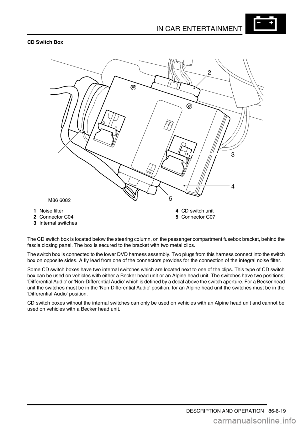
CD Switch Box
1Noise filter
2Connector C04
3Internal switches4CD switch unit
5Connector C07
The CD switch box is located below the steering column, on the passenger compartment fusebox bracket, behind the
fascia closing panel. The box is secured to the bracket with two metal clips.
The switch box is connected to the lower DVD harness assembly. Two plugs from this harness connect into the switch
box on opposite sides. A fly lead from one of the connectors provides for the connection of the integral noise filter.
Some CD switch boxes have two internal switches which are located next to one of the clips. This type of CD switch
box can be used on vehicles with either a Becker head unit or an Alpine head unit. The switches have two positions;
'Differential Audio' or 'Non-Differential Audio' which is defined by a decal above the switch aperture. For a Becker head
unit the switches must be in the 'Non-Differential Audio' position, for an Alpine head unit the switches must be in the
'Differential Audio' position.
CD switch boxes without the internal switches can only be used on vehicles with an Alpine head unit and cannot be
used on vehicles with a Becker head unit.
Page 1484 of 1529

INSTRUMENTS
DESCRIPTION AND OPERATION 88-1
INS TRUMENTS DESCRIPTION AND OPERAT ION
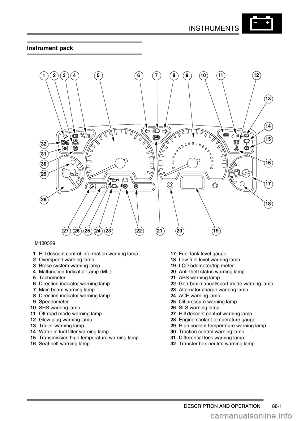
Instrument pack
1Hill descent control information warning lamp
2Overspeed warning lamp
3Brake system warning lamp
4Malfunction Indicator Lamp (MIL)
5Tachometer
6Direction indicator warning lamp
7Main beam warning lamp
8Direction indicator warning lamp
9Speedometer
10SRS warning lamp
11Off road mode warning lamp
12Glow plug warning lamp
13Trailer warning lamp
14Water in fuel filter warning lamp
15Transmission high temperature warning lamp
16Seat belt warning lamp17Fuel tank level gauge
18Low fuel level warning lamp
19LCD odometer/trip meter
20Anti-theft status warning lamp
21ABS warning lamp
22Gearbox manual/sport mode warning lamp
23Alternator charge warning lamp
24ACE warning lamp
25Oil pressure warning lamp
26SLS warning lamp
27Hill descent control warning lamp
28Engine coolant temperature gauge
29High coolant temperature warning lamp
30Traction control warning lamp
31Differential lock warning lamp
32Transfer box neutral warning lamp