1999 HONDA CR-V NEUTRAL SWITCH
[x] Cancel search: NEUTRAL SWITCHPage 78 of 1395

Gharging System
Troubleshooting (cont'd)
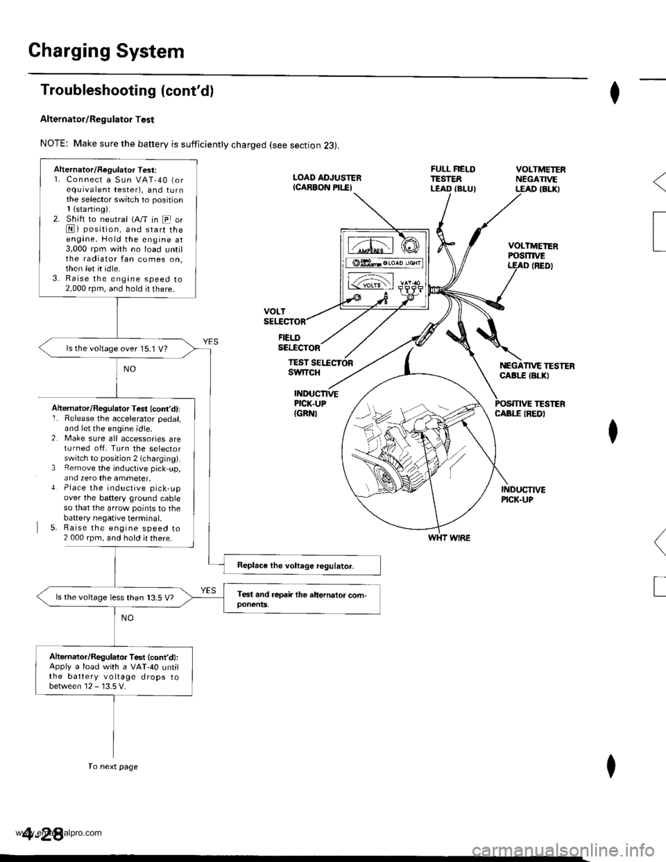
Alternator/Regulator Test
NOTE: Make sure the battery is sufficiently charged (see section 23).
FIELDSELECTOR
TESTswtTcH
I
VOLTMEIERPOSmVEt
NEGATIVE TESTERCABI.E {BLKI
(BED)
TESTERINDUCTIVEPICK.UP{GRN)CABLE IREDIAhernator/Regulator Test (cont'd)lI� Release the accelerator pedal,and let the engine idle.2 Make sure all accessories areturned off. Turn the selectorswitch to posjtion 2 (charging).3 Remove the inductive pick up,and zero the ammeter.{ Place the inductive pick-upover the battery ground cableso that the arrow points to thebaftery negative terminal.5. Raise the engine speed to2 000 rpm, and hold ir there.
I
(
T
I
WHT WIRE
Alternator/Regulator Test:1. Connect a Sun VAT-40 (orequrvalent tester), and turnthe selector switch to position1{sraning).2. Shift to neutral (A/T in E orN) position, and start theengane. Hold the engine at3,000 rpm with no load untilthe radiator fan comes on,then let it idle.3. Raise the engine speed to2,000 rpm, and hold it there.
ls the voltage over 15.1 V?
ls the voltage less than 13.5 V?
Altarnator/Regulator Test (cont'd:Apply a load with a VAT-40 untilthe battery voltage drops tobetween 12 - 13.5 V.
To next page
4-28
www.emanualpro.com
Page 93 of 1395

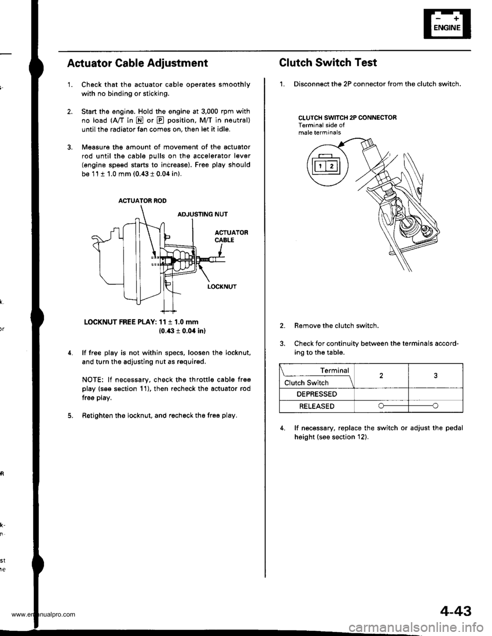
Actuator Cable Adiustment
'1.Check that the actuator cable operates smoothly
with no binding or sticking.
Start the engine. Hold the engine at 3,000 rpm with
no load (A,/T in E or E position, M/T in neutral)
until the radiator fan comes on, then let it idle.
Measure the amount of movement of the actuator
rod until ths cable pulls on the accelerator lever
(engine speed starts to increase). Free play should
be 11 t 1.0 mm (0.43 i 0.04 in).
LOCKNUT FREE PLAY: 11 t 1.0 mm
10.43 r 0.04 in)
lf free play is not within specs, loosen the locknut,
and turn the adjusting nut as requirsd,
NOTE: lf necessary, check the throttl€ cable frso
play (s€e section 11), then recheck the actuator rod
free play.
Retighten the locknut, and recheck the free play.
st
te
ACTUATOR ROD
Clutch Switch Test
1. Disconngct ths 2P connector from the clutch switch.
CLUTCH SWITCH 2P CONNECTORTerminalside ofmale terminals
2.
5.
Remove the clutch switch,
Check for continuity between the terminals accord-
ing to the table.
4. lf necessary, replace the switch or adjust the pedal
height (see section t2).
Terminal
Clutch Switch \
OEPRESSED
RELEASEDoo
4-43
www.emanualpro.com
Page 270 of 1395

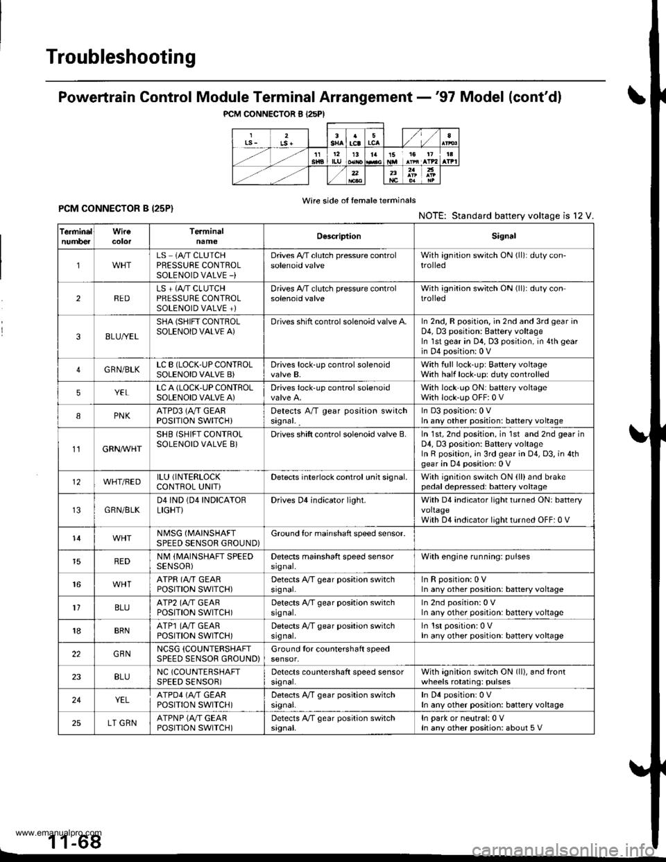
Troubleshooting
PCM CONNECTOR B I25PI
Powertrain Control Module Terminal Arrangement -'97 Model (cont'dl
Wire side of female terminalsPCM CONNECTOR B I25P}NOTE: Standard battery voltage is l2 V.
1 1-68L
TerminelnumbercolorTerminalnameOescriptionSignal
1LS 1A/T CLUTCHPRESSURE CONTROLSOLENOID VALVE -)
Drives A,/T clutch pressure controlsolenoid valveWith ignition switch ON (ll): duty con-trolled
2REDLS + (A"/T CLUTCHPRESSURE CONTROLSOLENOID VALVE +)
Drives A,/T clutch pressure controlsolenoid valveWith ignition switch ON (ll)r duty controlled
38LU//EL
SHA (SHIFT CONTROLSOLENOID VALVE A)Drives shift control solenoid valve A.In 2nd, R position. in 2nd and 3rd gear inD4, D3 position: Battery voltageIn lst gear in D4, D3 position, in 4th gear
in D4 position: 0 V
4GRN/BLKLC B (LOCK-UP CONTFOLSOLENOID VALVE B)Drives lock-up control solenoidvalve B,With full lock-up; Baftery voltageWith half lock-up: duty controlled
5YELLC A (LOCK.UP CONTROLSOLENOID VALVE A)Drives lock-up control solenoidWith lock'up ON: battery voltageWith lock-up OFF:0 V
IPNKATPD3 (Ay'T GEARPOSITION SWITCH}Detects A/T gear position switchsignal. _
In D3 position:0 Vln any other position: battery voltage
11GRN/VVHT
SHB (SHIFT CONTROLSOLENOID VALVE 8}Drives shift control solenoid valve B.In 1st, 2nd position, in 1st and 2nd gear inD4, D3 position: Battery voltageIn R position, ;n 3rd gear in 04, D3, in 4thgear in D4 position: 0 V
12WHT/BEDILU (INTERLOCK
CONTROL UNITiDetects interlock control unh signal.With ignition switch ON (ll)and brakepedal depressed: battery voltage
GRN/BLKD4IND (04 INDICATORLIGHT}Drives Dl indicator light.With D4 indicator light turned ON: batteryvoltageWith D4 indicator light turned OFF: 0 V
14NMSG (MAINSHAFT
SPEED SENSOR GROUND}Ground tor mainshaft speed sensor.
REDNM (MAINSHAFT SPEEDSENSOR)Detects mainshaft speed sensorsrgnal,With engine running: pulses
16ATPR (A"/T GEARPOSITION SWITCH)Detects A/T gear position switchsrgnal.InRposition:0VIn any other position: battery voltage
1'lBLUATP2 (A./T GEARPOSITION SWITCH)Detects A/T gear position switchsrg nal,In 2nd position: 0 VIn any other position: battery voltage
18BRNATP1 (4,,/T GEARPOSTTTON SWTTCH)Detects A/T gear position switchsrg nal,ln lst position: 0 VIn any other position: battery voltage
22GBNNCSG (COUNTERSHAFT
SPEED SENSOR GROUND)Ground tor countershaft speedsensor,
23BLUNC (COUNTERSHAFT
SPEED SENSOR)Detects countershaft speed sensorsrgnal.With agnition switch ON (ll), and lrontwheels rotating: pulses
24YELATPD4 (M GEARPOSITION SWITCH)Detects A,/T gear position switchsrgnal.In D4 positionr 0 VIn any other position: battery voltage
25LT GRNATPNP {A/T GEARPOSITION SWITCH)Detects A/T gear position switchsignal.In park or neutral:0 VIn any other position: about 5 V
www.emanualpro.com
Page 294 of 1395
![HONDA CR-V 1999 RD1-RD3 / 1.G Workshop Manual
PGM-FI System
Manifold Absolute Pressure (MAP) Sensor (contd)
[tn,t nn-] The scan tool indicates Diagnostic Trouble Code (DTC) P0108: A high voltage (low vacuum) problem in the|jg Manifold Absolute HONDA CR-V 1999 RD1-RD3 / 1.G Workshop Manual
PGM-FI System
Manifold Absolute Pressure (MAP) Sensor (contd)
[tn,t nn-] The scan tool indicates Diagnostic Trouble Code (DTC) P0108: A high voltage (low vacuum) problem in the|jg Manifold Absolute](/manual-img/13/5778/w960_5778-293.png)
PGM-FI System
Manifold Absolute Pressure (MAP) Sensor (cont'd)
[tn,t nn-] The scan tool indicates Diagnostic Trouble Code (DTC) P0108: A high voltage (low vacuum) problem in the|jg Manifold Absolute Pressure (MAP) sensor.
MAP SENSOR 3P CONNECTOR IC131I
Wire side of female terminals
vcclIYEL/RED}
PCM CONNECTOR D I16PI
JUMPER WIRE
sGlIGRN/WHTI
Wire side of lemale termin6ls
1
(To page 11,93)': '98 - 00 models
1-92
tcRN/wHrll IIRED/GRN|
The MIL has boen reported on.DTC m108 is slored.
Problem veritication:1. Start the engine. Hold theengine at 3,000 rpm with noload (in Park or neutral) untilthe radiator fan comes on, thenlet it idle.2. Check the MAP with the scantool.
Intermittent tailuro, system i3 OKat this time. Check tor ooor con-nections or loose wires at C131IMAP s6nsor) snd the ECM/rcM.
ls 101 kPa {760 mmHg,30 in.Hg),2.9 V or higher indicated?
Check Ior an open in the MAPsensor:1. Turn the ignition switch OFF.2. Disconnect the MAP sensor3P connector.3. lnstall a jumper wire betweenthe MAP sensor 3P connectorterminals No.3 and No.2.4. Turn the ignition switch ON {ll).5. Check the MAP with the scantool.
ls 10'l kPa (760 mmHg,30 in.Hg),2.9 V or higher indicated?
Check for an open in wire (SGlliDel:1. Remove the jumper wire.2. Measure voltage between theMAP sensor 3P connector ter-minals No. 1 and No- 2.
R6p.ir open in the wire betwoenthe ECM/PCM (D12, CTrl and theMAP sensor.
ls there approx. 5 V?
Check for an open in the wire(MAP line):1. Turn the ignition switch OFF.2. lnstall a iumper wire on thePCM connectors between D3and D12.3. Turn the ignition switch ON (ll).4. Check the MAP wirh the scantool.
Ropair opon in the wire betweenthe PCM {D3, .nd the MAP son-3('t.
ls 101 kPa 1760 mmHg, 30 in.Hg),2.9 V or higher indicated?
YES
www.emanualpro.com
Page 296 of 1395

PGM-FI System
Manifold Absolute Pressure (MAP) Sensor (cont'dl
The scan tool indicates Diagnostic Trouble Code (DTC) P1128: Manifold Absolute pressure (MAp) lower thanexoected.
The scan tool indicates Diagnostic Trouble Code (DTC) P'l129: Manifold Absolute Pressure (MAP) higher thanexpected.
l
- The MIL has be6n r€ported on.- DTC Pl128 is stored.
Problom verification:1. Turn the ignition switch ON 1lli.2. Check the MAP with the scantool,
ls 54.1 kPa (406 mmHg, 16.0 in.Hg),1.61 V or higher indicated?I to.mittent failure, 3ydom i! OKal thbtimc,
- The MIL has boen reportod on.- DTC Pl129 is stored.
Problem veritication:1. Start the engine. Hold theengine at 3,000 rpm with noload lin Park or neutral) untilthe radiator fan comes on,then Iet it idle.2. Check the MAP with the scantool,
ls 43.3 kPa (325 mmHg, 12.8 in.Hg),'1.32 V or less indicated?Intarmittani fuilure, systom i3 OKat this time.
11-94
www.emanualpro.com
Page 305 of 1395

Throttle Position (TPl Sensor
The scan tool indicates Diagnostic Trouble Code (DTC) P0122: A low input (voltage) problem in the Throttle
Position (TP) sensor circuit.
The TP Sensor is a potentiometer. lt is connocted to the throttle valve shaft. As the throttle position changes, the throftle
position sensor varies the voltage signal to the ECM/PCM.
'97 mod6l:BRUSHHOI,I'ER
OUTPUT VOLTAGE IVI
5
4
3
2
1
0
THROITLEOPCNIiIG
FUTIIHROTTI"E
TP SENSOR 3P CONNECTOR {Cl3OI
vcc2IYEL/BLUI
Wi.6 6ide ot fgmale terminsls
PCM CONNECTOR D I16PI
Wire side of female terminals
(GRN/BLX)
- The MIL h.3 been reoorted on.- OTC m122 b 3tored.
Problem vorificalion:1. Start the engine. Hold theengine at 3,000 rpm with noload (in Park or neutrall untilthe radiator fan comes on,then turn the ignition switchOFF.2. Turn the ignition switch ON (ll).
3. Check the throttle position
with the scan tool.
ls there approx. 10% when thethrottle is fully closed andapprox.90% when the throttleis fully opened?
Intormittent feilu?e, 3y3tem is OKat thb iime. Check tor poor con-nodiona or loose wiros at C130tTP loNorl .nd rt th€ PCM.
Check tor an open in the wire{vOC2linel:1. Turn the ignition switch OFF.2. Disconnect the TP sensor 3Pconnector,3. Turn the ignition switch ON lll).il. Measure voltage betweenthe TP sensor 3P connector ter-minals No. 1 and No. 3.
ls there approx.5 V?
Check to. an open in wir6 {VCC2linel:Measure voltage between PCMconnector terminals 010 and D11.
Ch6ck to. an opon or shon in TPsonaol:1. Turn the ignition switch OFF.2, At the sensor side, measureresistance between the TPsensor 3P connector terminalsNo. 1 and No. 2 with the throt-tle fully closed.
Repair open in the wirc betweenPCM {D10} and TP 3ensor.ls there approx. 5 V?
Sub3tituto . known-good PCMand rechock. It proscribed volt-ag. b now availablo. rcplaco th6originsl PCM,
Terminal side of male terminals(cont'd)
(To page 11-104)
1 1-103
www.emanualpro.com
Page 307 of 1395

'98 - 00 model3:
The MIL has boon reDortod on.DTC m122 b rtorod.
P.oblom veiification:1. Start the engine. Hold theengine at 3,000 rpm with noload (in Park or neutral) untilthe radiator tan comes on,then turn the ignition switchOFF.2. Turn the ignition switch ON lll).3. Check the throttle position
with the scan tool.
ls there approx. 10% when thethrottle is fully closed andapprox. 90% when the throttleis fully opened?
Intarmittent failure. system is OKat thia time. Check for poor con-n€ctions or loolo wires rt C130ITP s.nsorl and.t the ECM/FCM.
Check for an opon or short in thowire {VCC2 linel:1. Turn the ignition switch OFF.2. Disconnect the TP sensor 3Pconnedor,3. Turn the ignition switch ON (ll).
4. Meas! re voltage betweenthe TP s€nsor 3P connector ter-minals No. 1 and No.3.
ls there approx. 5 V?
Check lor an opon in wiro IVCC2linel:Measure voltage between ECM/rcM connector terminals C'18 andc2a.Chock for en op€n or Bhort in TP3an30r:1. Turn the ignition switch OFF.2. At the sensor side, measureresistance between the TPsensor 3P conneclor terminalsNo. 1 and No. 2 with the throt-tle fully closed.
B.psir opon in the wire b€{woontho ECM/PCM {C281 and th6 TP3en!xtt.ls lher€ approx. 5 V?
Subslitute e known-good ECM/PCM .nd r.chock. lf pro3cribedvoltrge iB now rYrilablo, replacath. originll ECM/PCM.
TP SENSOR 3P CONNECTOR {C130}
sG2IGRN/BLKI
vcc2IYEUBLUI
Wire side oI Iemale lerminals
Wire sid6 of temale terminals
Terminal side of male torminals
(cont'd)
1 1-105
ECM/PCM CONNECTOR C (31P}
sG2IGRN/BLKIa-,l 18 sl./|135
/1617lrs]zolzr zzl
232527)gJ lzgi3o sr I
T^vccz {YEL/8LUl
(To page 11-106)
www.emanualpro.com
Page 309 of 1395
![HONDA CR-V 1999 RD1-RD3 / 1.G Workshop Manual
The scan tool indicates Diagnostic Trouble Code (DTC) P0123: A high voltage problem in the Throttle Position
(TP) sensor circuit.
TP SENSOR 3P @]{NECTOR IC13O}
sG2(GnN/Br.XlvocrtYEt /8LU)
{GBIT/BLKI
HONDA CR-V 1999 RD1-RD3 / 1.G Workshop Manual
The scan tool indicates Diagnostic Trouble Code (DTC) P0123: A high voltage problem in the Throttle Position
(TP) sensor circuit.
TP SENSOR 3P @]{NECTOR IC13O}
sG2(GnN/Br.XlvocrtYEt /8LU)
{GBIT/BLKI](/manual-img/13/5778/w960_5778-308.png)
The scan tool indicates Diagnostic Trouble Code (DTC) P0123: A high voltage problem in the Throttle Position
(TP) sensor circuit.
TP SENSOR 3P @]{NECTOR IC13O}
sG2(GnN/Br.XlvocrtYEt /8LU)
{GBIT/BLKI
(cont'd)
11-107
Wiro side of fom.le terminals
PCM CON'{ECTOF D I16PI
Wire side ot female terhinals
The MIL hlr br€n r.9ort.d on.DTC P0123 ir stored.
Pioblom vorificltion:1. Start the ongin6. Hold th€ongine at 3,000 rpm with noload {in Park or neutral) untilth6 radiator fan comes on.then turn the ignition switchOFF,2. Turn the ignition switch ON (ll).
3. Check the throttle position
with the scan tool.
Intarmittant tailuro, ryrtern b OKat this timo. Chock lor poor con-nections or loo3o wir€3 at C130
ITP 3orcorl .nd at tho ECM/FCM.
ls there spprox. 1oyo when thothrottle is Iully closed andapprox.90% when the throttleis tully open€d?
Choct toJ an opcn in th6 TP s6n-3t']:1. Turn the ignition switch OFF.2. Disconnect the TP sensor 3Pconnectol,3. Turn the ignition switch ON (ll).
4. At the wir6 harnoss side, mea-suro voltage betweon thg TPsensor 3P connector t€rminalsNo. 1 and No.3.
ls there approx.5 V?
Chack for an oDan in tha wira(SG2 linel:M6asu16 voltage b6tween PCMconn€ctor terminals Dl0 and D'! 1.
R.pai. opcn in tha wira botwcontho PcM {o111 rnd the TP 3en-3('t,
ls there approx. 5 V?
('97 model)
(To page 11-108)
www.emanualpro.com