Page 1295 of 1395
-
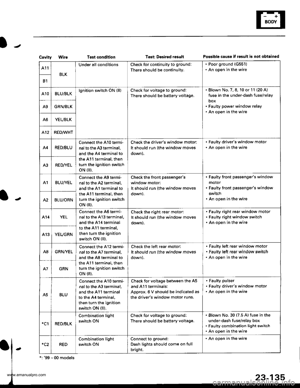
CavityWi1€Test conditionTesi: Dssired rosultPo$ible cause if 183uh is not obtained
A11
BLK
Under all conditionsCheck for continuity to ground:
There should be continuity.
. Poor ground (G551)
. An open in the wire
B1
A10BLU/BLKlgnition switch ON (ll)Check for voltage to ground:
There should be battery voltage.
Blown No. 7, 8, 10 or l1 (20 A)
fuse in the under-dash fuse/relay
box
Faulty power window relay
An open in the wire
A9GRN/BLK
A6YEUBLK
412RED/WHT
A4RE D/BLU
Connect the A10 termi-
nal to the 43 terminal,
and the A4 terminal to
the A11 terminal, then
turn the ignition switch
oN flr).
Check the driver's window motor:
It should run (the window moves
down).
. Faulty driver's window motor
. An open in the wire
A3RED/YEL
A1BLUI/EL
Connect the A9 termi-
nal to the A2 terminal,
and the Al terminal to
the 411 terminal, then
turn the ignition switch
oN flr).
Check the front Passenger'swindow motor:
It should run (the window moves
down).
Faulty front passenger's window
motor
Faulty front passenger's window
switch
An open in the wireA2BLU/ORN
A14YEL
Connect the 46 termi-
nalto the A13 terminal,
and the 414 terminal
to the A11 terminal,
then turn the ignition
switch ON (ll).
Check the right rear motor:
It should run (the window moves
oown).
Faulty right rear window motor
Faulty right window switch
An open in the wire
YEUGRN
A8GBN/YEL
Connect the A12 termi-
nal to the A7 terminat,
and the A8 terminal to
the A11 terminal. then
turn the ignition switch
oN flr).
Check the left rear motor:
,t should run {the window moves
down),
Faulty left rear window motor
Faulty ,eft rear window srrvitch
An open in the wire
GRN
A5BLU
Connect the A10 te.mi-
nal to the 43 terminal,
and the A11 terminal
to the 44 terminal.
then turn the ignition
switch ON (ll).
Check for voltage between the A5
and Al l terminals:
ADorox.6 V should be indicated as
the driver's window motor runs.
Faulty pulser
Faulty driver's window motor
An open in the wire
*clRED/BLK
Combination light
switch ON
Check fo. voltage to ground:
There should be battery voltage.
Blown No.30 (7.5 A) fuse in the
under-dash fuse/relay box
Faulty combination light switch
An open in the wire
RED
Combination light
switch ON
Connect to ground:
Dash lights should come on full
bright.
' An open in the wire
www.emanualpro.com
Page 1318 of 1395
JWiring Precautions
. Never attempt to modify, splice or repair SRS wiring.
NOTE: SRS wiring can be identified by special yellow
outer coveflng.
Be sure to install the harness wires so that they are
pinched or interfering with other parts.
Make sure all SRS ground locations are clean and
grounds are securely fastened for optimum metal-to-
metal contact. Poor grounding can cause intermittent
problems that are difficult to diagnose.
GROUND TERMINAL
CONTACT
CONTACT
24-21
Spring-loaded Lock Connestor with
Built-in Short Gontact
The driver's airbag/front passenger's airbag and seat
belt tensioners have a spring-loaded lock connector with
a built-in short contact. When this connector is discon-
nected, the power terminal and the ground terminal in
the airbag connector are automatically shorted.
Conngctor halvcs diSconnested:
GROUND TERMINAL
SHORT CONTACT
CABIf REEL CONNECTOR
Connector halves connected;
ACT
www.emanualpro.com
Page 1326 of 1395
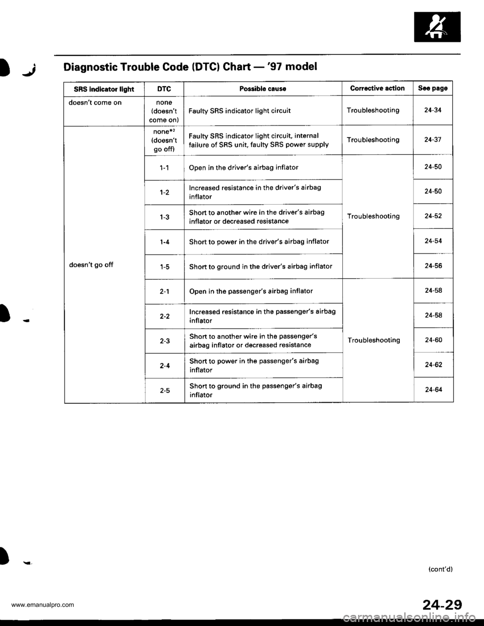
jIDiagnostic Trouble Code (DTG) Ghart -'97 model
SRS indicator lightDTCPos3ibls causeCorroctive actionSlc pago
doesn't come onnone(doesn't
come on)
Faulty SRS indicator light circuitTroubleshooting24-34
doesn't go off
none*'�(doesn't
go off)
Faulty SRS indicator light circuit, internal
tailure of SRS unit, faulty SBS power supplyTroubleshooting24-37
Open in the driver's airbag inflator
Troubleshooting
24-50
Increased resistance in the driver's airbag
inflator24-50
Short to another wire in the driver's airbag
inflator or decreased resistance24-52
Short to power in the driver's airbag inflator24-54
Short to ground in the driver's airbag inflator24-56
Open in the passenger's airbag inflator
Troubleshooting
24-58
Increased resistance in the passenger's airbag
inflator24-54
Shon to another wire in the passenger's
airbag inflator or decreased resistance24-60
2-4Short to power in the passenger's airbag
inflator24-62
2-5Shon to ground in the passengar's airbag
inflator24-64
)r,(cont'd)
24-29
www.emanualpro.com
Page 1328 of 1395
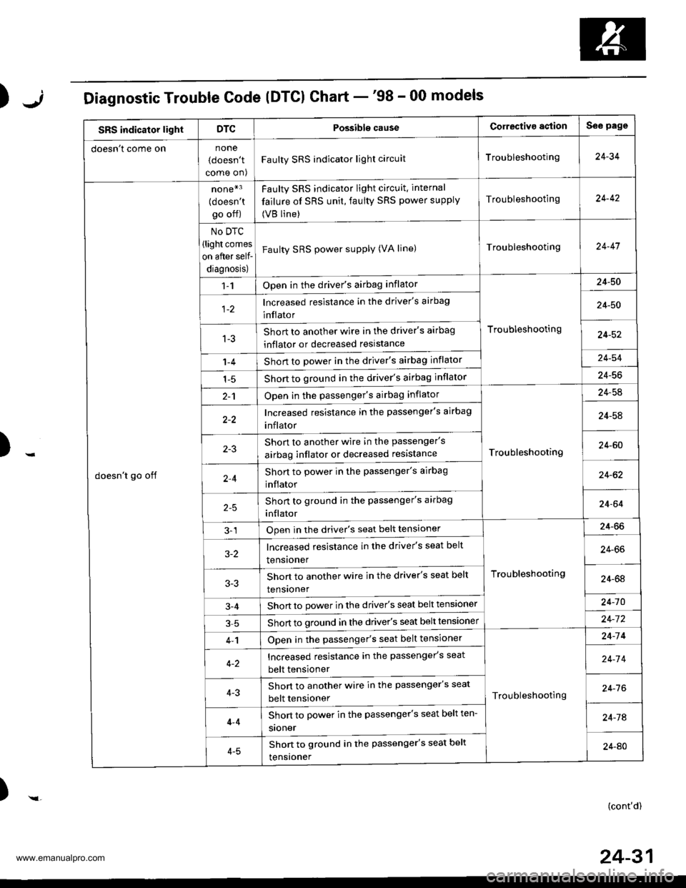
);Diagnostic Trouble Code (DTCI Chart -'98 - 00 models
SRS indicator lightDTCPossibls causeCorrectiva agtionSee page
doesn t come onnone
(doesn't
come on)
Faulty SRS indicator light circuitTroubleshooting24-34
doesn't go off
none*3
{doesn'tgo off)
No DTC
(light comes
on after self-
diagnosis)
Faulty SRS indicator light circuit. internal
failure of SRS unit, faulty SRS power supply
(VB line)
Troubleshooting24-42
Faulty SRS power supply (VA line)Troubleshooting24-47
1-1Open in the driver's airbag inflator
Troubleshooting
24-50
lncreased resistance in the driver's airbag
inflator24-50
1-3Short to another wire in the driver's airbag
inflator or decreased reslstance24-52
1-4Short to power in the driver's airbag inflator24-54
1-5Short to ground in the driver's airbag inflator24-56
2-1Open in the passenger's airbag inflator
Troubleshooting
24-54
Increased resistance in the passenger's airbag
inflator24-58
Shon to another wire in the passenger's
airbag inflator or decreased resistance24-60
2,4Short to power in the passenger's airbag
inflator24-62
Short to ground in the passenger's arrbag
inflator24-64
3-1Open in the driver's seat belt tensioner
Troubleshooting
24-66
3-2lncreased resistance in the driver's seat belt
tensroner24-66
Shon to another wire in the driver's seat belt
tensroner24-64
3-4Short to power in the driver's seat belt tensioner24-10
Short to ground in the driver's seat belt tensloner24-7 2
4-1Open in the passenger's seat belt tensioner
Troubleshooting
24-14
Increased resistance in the passenger's seat
belt tensioner24-7 4
4-3Short to another wire in the passenger's seat
belt tensioner24-7 6
4-4
4-5
Short to power in the passenger's seat belt ten-
sroner24-74
Shon to ground in the passenger's seat belt
tensroner24-AO
)-(cont'd)
24-31
www.emanualpro.com
Page 1330 of 1395
SRS Indicator Light Wire Connections
SRS Indicator Light Power Circuit
DASHBOARD WIRE HARNESS
YEL
BLK
To UNDER-DASHFUSE/RELAY BOX <_
20P CONNECTOR
To GAUGEcsog + assEMBLy
SRS Indicator Light Control Circuit
SRS MAIN HARNESS
)-MAIN WIRE HARNESS
VAIVBIt
To UNDER-DASHFUSE/BELAY BOX2P CONNECTOR
c414MAIN WIRE HARNESS 3P CONNECTORTerminal side of msle t€rminals
c415MAIN wlRE HARNESS 24P CONNECTORTerminal aide of male terminals
c502DASHBOARD WIRE HARNESS 2OP CONNECTORWire side of lemslo terminsls
c503OASHBOARD WIRE HARNESS 24P CONNECTORWire side of female t€rminal3
c509DASHBOABD WIRE HARNESS 5P CONNECTORWire sid€ ot lemale te.minals
c801SRS MAIN HARNESS 2P CONNECTORwire side ol f.male terminals
c803SRS MAIN HARNESS 3P CONNECTORWire side ol female terminals
c806SRS MAIN HARNESS T8P CONNECTORWire side of lomrle terminals
)
24-33
www.emanualpro.com
Page 1331 of 1395
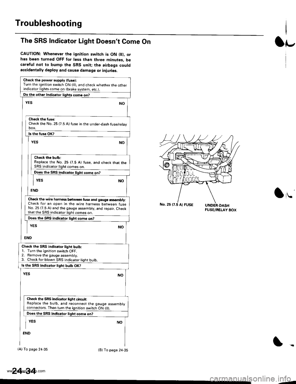
Troubleshooting
The SRS Indicator Light Doesn't Come On
CAUTION: Whenever the ignition switch is ON D, orhas been turned OFF for less than three minutes, becareful not to bump the SRS unit; the airbags couldaccidentally deploy and cause damage or iniuries.
Ch6ck the power supply (fuse):Turn the ignition switch ON {ll), and check whether the otherindicator lights come on (brake system, e(c.r.
Do the other indicator liglrts com6 on?
Check the No. 25 (7.5 A) fuse in the under-dash tuse/relayDOX.
ls the tus€ oK?
NO
Check the bulb:Replace the No.25 (7.5 A) fuse, and check that theSRS indicator light comes on.
Does the SRS indicator liqht come on?
YESNO
END
YES
Check the wire h.rnesi kwe€n fus€.nd gauge .3sembly:Check for an open in the wire harness between fuseNo. 25 (7.5 Al and the gauge assembly, and repair. Checkthat lhe SRS indicato.lighi
Does the SRS indic.tor liqht com6 on?
END
YESNO
Check the SRS indicator light bulb:1. Turn the ignition switch OFF.2. Remove the gauge assembly.3. Check lor blown SRS indicator tight bulb.
ls the SRS indicator tight bulb OK?
YESNO
Check the SRS indicator light circuit:Replace the bulb, and reconnect the gauge assemblyconneclors. Then turn the ignition switch ON {ll).
Does the SRS indicator light come on?
I YEs No
:ND
(A) To page 24-35(B) To page 24 35
24-34
lr-
lu
-J
www.emanualpro.com
Page 1333 of 1395
Troubleshooting
From page 24-35
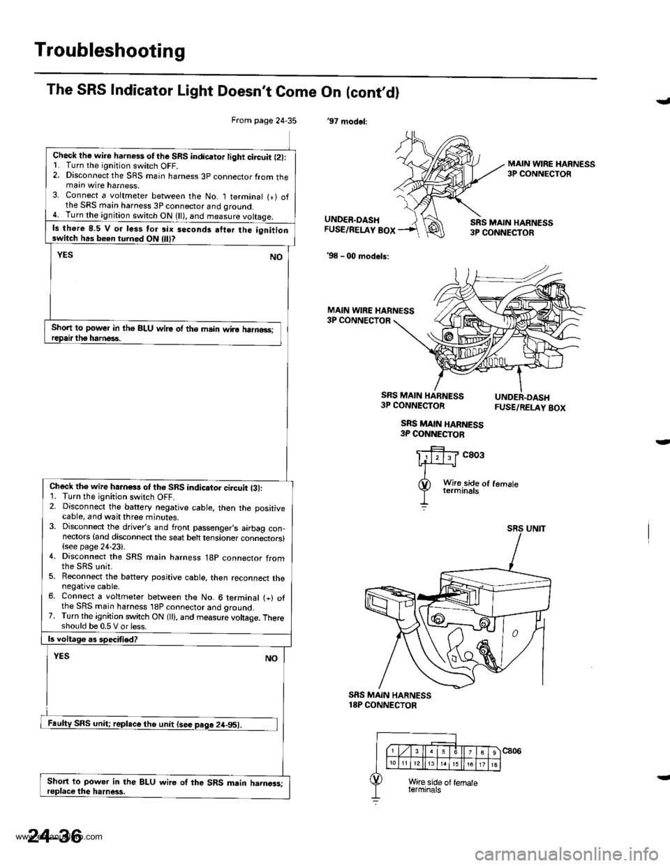
Check lhe wire harness otthe SRS indicator light circuit l2l:L Turn the ignitjon switch OFF.2. Disconnect the SRS main harness 3p connector from themain wire harness.3. Connect a voltmeter between the No. I terminal (+) ofthe SRS main harness 3P connector and qround.4. Turn the ignition switch ON (ll), and measure voltaqe.
ls there 8.5 V o. less tor six seconds atter the ignitionswitch has been turned ON
Short to power in th€ BLU wire of the main wiro halno3s;
Check th€ wire hahess of th6 SRS indicator ci.cuit {31:1. Turn the ignition switch OFF.2. Disconnect the battery negative cable, then the positivecable, and wait three minutes.3. Disconnect the driver's and front passenger,s airbag con-nectors {and disconnect the seat belt tensioner connectors}(see page 24-23).4. Disconnect the SRS main harness 18p connector from
5. Reconnect the battery positive cable, then reconnect thenegative cable.6. Connect a voltmeter between the No. 6 terminal (+) ofthe SRS main harness 'l8P connector and ground.7. Turn the ignition switch ON (ll), and measure voltage. Thereshould be 0.5 V or less.
Short to power in the BLU wire oI the SRS main harngas;
The SRS Indicator Light Doesn't Come On (cont,dl
'97 modol:
J
MAIN WIRE HARNESS3P CONNECTOR
UNDER.DASHFUSE/RELAY BOX
'98 - 00 models:
SRS MAIN HARN€SS3P CONNECTOR
MAIN WIRE HARNESS3P CONNECTOR
SRS MAIN HARNESS3P CONNECTOR
SRS MAIN HARNESS3P COI{NECTOB
FUSE/RELAY BOX
c803
SRS MAIN HARNESS18P CONNECTOR
24-36
www.emanualpro.com
Page 1368 of 1395
)
From page 24-70
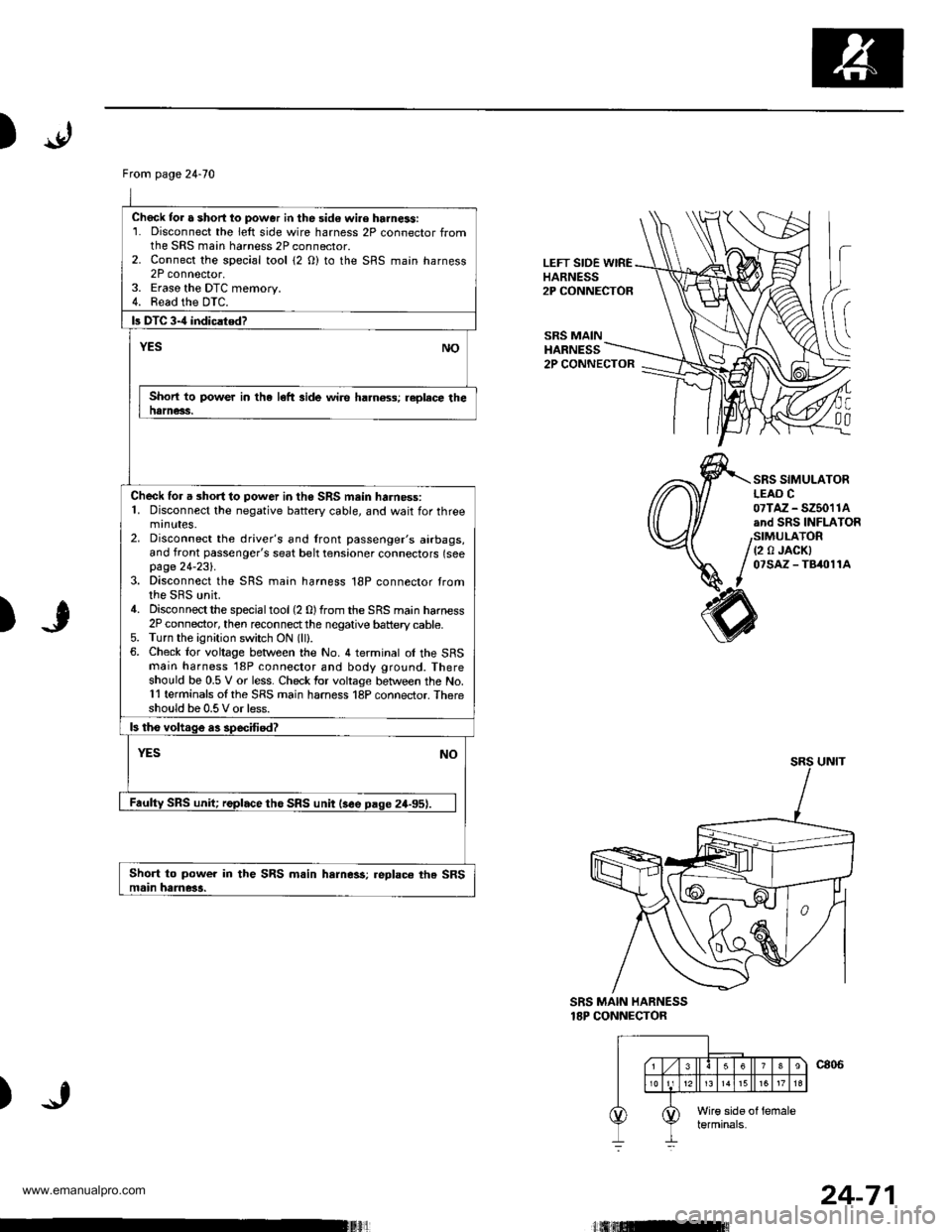
Chock tor a short lo power in the sid€ wi.e harness:1. Disconnect the left side wire harness 2P connector fromthe SRS main harness 2P connector.2. Connect the sDecial tool {2 O) to the SRS maan harness2P connector,3. Eraso the DTC memory.4. Read the DTC.
b DTC 3-4 indiclted?
NOYES
Short to power in the left side wire ha.n6ss; replece thenarness.
Check for a short to power in the SRS mein harness:1. Disconnect the negative battery cable, and wait for threemrnutes.2. Disconnect the driver's and lront passenger's airbags,and front passenger's seat belt tensioner connectors (seepage 24-231.3. Disconnect the SRS main harness 18P connector tromthe SRS unit.4. Disconnectthe specialtool(2 0)from the SRS main harness2P connector, then reconnectthe negative battery cable.5. Turn the ignition switch ON (lll.6. Check lor voltage between the No. 4 terminal ol the SFSmain harness '18P connector and body ground. Thereshould be 0.5 V or less. Check for voltage between the No.11 terminals ol the SRS main harness 18P connector. Thereshould be 0.5 V or less.
ls tho voltage as specffied?
YESNO
Faulty SRS unit; replace tho SRS unit lsee paqe 24-95).
Short to power in the SRS m.in harness;.eplace the SRSmain hame3a.
LEFT SIDE WIREHARNESS2P CONNECTOR
SRS MAINHARNESS
h
(
C
00
2P CONNECTOR
SRS SIMULATORLEAO C07TAZ - SZ5011Aand SRS INFLATOR
(2 0 JACKI07SAZ - TB/t011A
)
SRS MAIN HARNESS18P CONNECTOR
)
24-71
www.emanualpro.com