Page 1287 of 1395

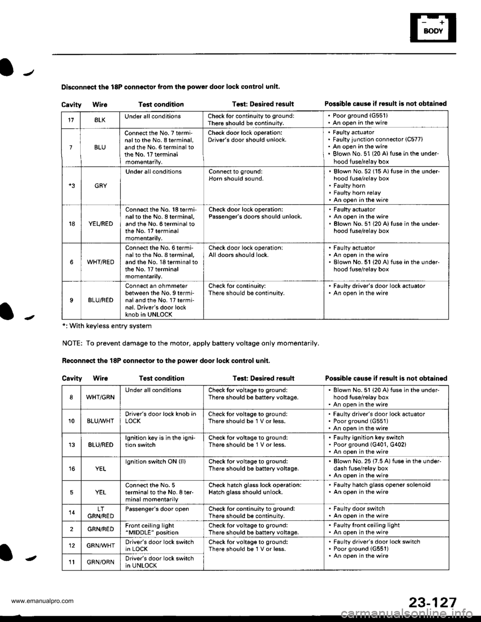
Disconnoci the 18P connestor from the pow€r door lock control unit.
Cavity WireTest conditionTost: Dcsired resultPo$ible csuse il result is not obtainod
Possible cause if result is not obtain€d
*: With keyless entry system
NOTE: To prevent damage to the motor, apply battery voltage only momentarily.
Feconnoct the 18P conneqtor to the power door lock control unit,
Cavity Wir6Test conditionTost: D€sirod result
118LKUnder all conditionsCheck for continuity to ground:
Ther€ should be continuity.
. Poorground (G55'l). An open in the wire
7BLU
Connect the No. 7 termi'nalto the No. 8 terminal,and the No. 6 terminal tothe No. 17 terminalmomentarily.
Check door lock operation:Driver's door should unlock.Faulty actuatorFaulty junction connector (C577)
An open in the wireBlown No. 51 (20 Al{use in the under-
hood fuse/relay box
GRY
Under all conditionsConnect to ground:Horn should sound,Blown No. 52 (15 A)tuso in the under-hood fuse/relay boxFaulty hornFaulty horn relayAn open in tho wire
YEURED
Connect the No. 'l8 termi-nalto the No. 8 terminal,and the No. 6 terminal tothe No. 17 terminalmomentarily.
Check door lock operation:Passenger's doors should unlock.Faulty actuatorAn open in the wireBlown No.51 (20 A)fuse in the under-hood fuse/relay box
WHT/RED
Connect the No.6termi-nal to th6 No. I terminal,and the No. 18 terminal tothe No. 17 terminalmomentarily.
Check door lock operationlAll doors should lock.Faulty actuatorAn open in the wireBlown No. 51 {20 A) fuse in ihe under-hood fuse/relay box
9BLU/RED
Connect an ohmmeterbetween the No. 9 termi-nal and the No. l7 termi-nal. Driver's door lockknob in UNLOCK
Check for conlinuity:There should be continuity.
' Faulty driver's door lock actualor. An open in the wire
WHT/GRNUnder all conditionsCheck for voltage to ground:
There should be battery voltage.Blown No. 51 (20 Alfuse in the under-hood tuse/relay boxAn open in the wire
10BLUAVHTDriver's door lock knob inLOCKCheck tor voltage to ground:There should be 1 V or less.Faulty driver's door lock actuatorPoor ground (G551)
An open in the wire
13BLU/REDlgnition key is in the igni-tion switchCheck tor voltage to ground:
There should b€ 1 V or less.Faulty ignition key switchPoor ground (G401, G402)An open in the wire
YELlgnition switch ON (ll)Check for voltage to ground:
There should be battery voltage.Blown No. 25 (7.5 A) fuse in the under-dash fuse/relay boxAn open in the wire
5YELConnect the No. 5terminal to the No. I ter-minal momentarily
Check hatch glass lock operation:Hatch glass should unlock.
. Faulty hatch glass opener solenoid. An opon in the wire
14LTGRN,NEDPassengor's door openCheck for continuity to ground:There should b€ continuity.
. Fa(llty door switch. An open in the wire
2GRN/R€DFront ceiling light"MlDDLE" positionCheck tor voltage to ground:There should be battery voltage.Faulty lront ceiling lightAn open in the wire
12GRNAr'VHTDriver's door lock switchin LOCKCheck lor voltage to ground:There should be 1V or less.Faulty driver's door lock switchPoor ground {G551)An open in the wire' GRN/ORNDriver's door lock switchin UNLOCK-
23-127
www.emanualpro.com
Page 1288 of 1395
Power Door Locks
Driver's Door Lock Knob Switch Test
1. Remove the driver's door panel (see section 20).
2. Disconnect the 6P connector from the actuator.
Terminalside otmale terfiinals
Check for continuity between the terminals in each
switch position according to the table.
rsrmrnal
Position \
?6
LOCKo--o
UNLOCKo---o
23-128
.
6P CONNECTOR
Driver's Door Lock Actuator Test
1, Remove the driver's door panel (see section 20).
2. Disconnect the 6P connector from the actuator.
Terminal side ofmale terminals
Check actuator operation by connecting power and
ground according to the table. To prevent damsge
to the actuator. apply battery voltage only momen-
tarilv,
6P CONNECTOR
Terminal
F*'',1."
__l
LOCK@o
UNLOCK@
'-
www.emanualpro.com
Page 1289 of 1395
Passenger's Door Lock Actuator Test
Remove the passenger's door panel (see section 20).
Disconnect the 2P connector from the actuator.
NOTE: The left rear door lock actuator is shown;
the front passenger's and right rear door lock actua-
tors are similar.
Terminal side ofmale terminals
Check actuator operation by connecting power and
ground according to the table. To prevent damage
to the actuator, apply battery voltage only momen-
raflry.
Terminal
;;il;--r
,l
LOCK@
UNLOCK@
1.
2P CONNECTOR
4. lf the actuator does not work properly, replace it.
23-129
L
Driver's Door Lock Switch Test
Remove the inner handle {see section 20).
Disconnect the 3P connector. then remove the two
mounting screws and driver's door lock switch.
Check for continuitv between the terminals in each
switch position according to the table.
lermlnal
Position \
123
LOCKo---o
OFF
UNLOCKo--_o
www.emanualpro.com
Page 1290 of 1395

Power Door Locks
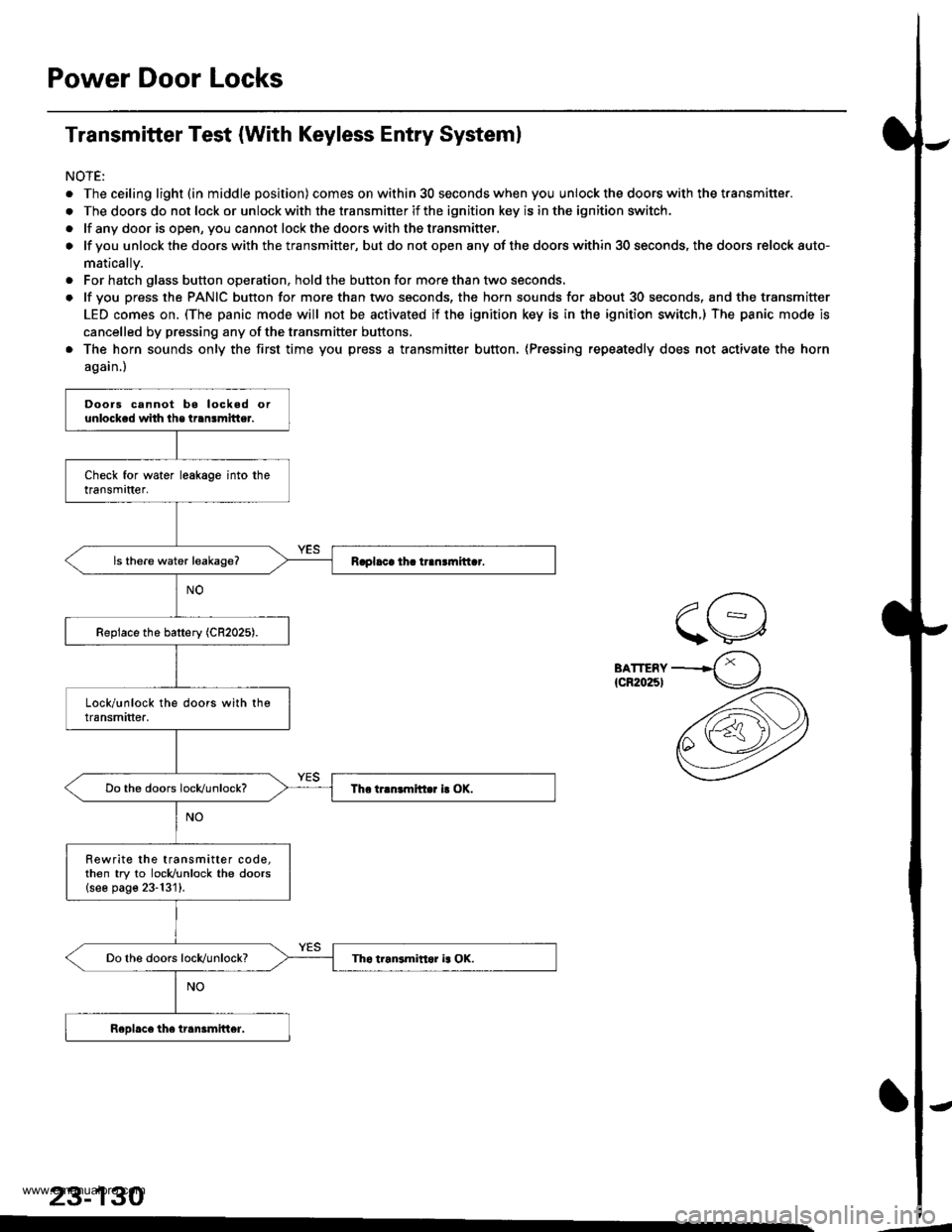
Transmitter Test (With Keyless Entry Systeml
NOTE:
. The ceiling light (in middle position) comes on within 30 seconds when you unlock the doors with the transmitter.
. The doors do not lock or unlock with the transmitter if the ignition key is in the ignition switch.
. lf any door is open, you cannot lockthe doorswith thetransmitter.
o lf you unlock the doors with the transmitter, but do not open any of the doors within 30 seconds, the doors relock auto-
matically.
. For hatch glass button operation, hold the button for more than two seconds.
. lf you press the PANIC button for more than two seconds, the horn sounds for about 30 seconds, and the transmitter
LED comes on. (The panic mode will not be activated if the ignition key is in the ignition switch.) The panic mode is
cancelled by pressing any of the transmitter buftons.
. The horn sounds only the first time you press a transmitter button, (Pressing repeatedly does not activate the horn
again.)
BATTERY{cR20251
23-130
Doors cannot bo locked orunlocked whh lhe transmitter.
Rewrite the transmitter code,then try to locldunlock the doors{see page 23-131}.
www.emanualpro.com
Page 1318 of 1395
JWiring Precautions
. Never attempt to modify, splice or repair SRS wiring.
NOTE: SRS wiring can be identified by special yellow
outer coveflng.
Be sure to install the harness wires so that they are
pinched or interfering with other parts.
Make sure all SRS ground locations are clean and
grounds are securely fastened for optimum metal-to-
metal contact. Poor grounding can cause intermittent
problems that are difficult to diagnose.
GROUND TERMINAL
CONTACT
CONTACT
24-21
Spring-loaded Lock Connestor with
Built-in Short Gontact
The driver's airbag/front passenger's airbag and seat
belt tensioners have a spring-loaded lock connector with
a built-in short contact. When this connector is discon-
nected, the power terminal and the ground terminal in
the airbag connector are automatically shorted.
Conngctor halvcs diSconnested:
GROUND TERMINAL
SHORT CONTACT
CABIf REEL CONNECTOR
Connector halves connected;
ACT
www.emanualpro.com