Page 719 of 1395
Inspection
Clearance Measurement
1. Remove the mainshaft bearing from the transmis-
sion housing lsee page 14-227l..
2. Assemble the mainshaft parts, but do not install the
O-rings,
CONICAL SPRING WASHER
SNAP RII{G
lST CLUTCH ASSEMELY
THRUST WASHER
1ST GEAB COLLAR
TRAI{SMISSIONHOUSIf{G BEARING
THRUST WASI{ER
2[{D/4TH CLUTCHASSEMALY
GEAR COLLAR
THRUST WASHER.5r55mmSelective part
THBUST IIEEDLEEEARII{G
2ND G€AR
EEARIt{G
TI{RUST NEEOLEBEARII{G
MAII{SHAFT
3. Tighten the mainshaft locknut to 29 N.m (3.0 kgf.m,
22 tbf.ft).
The mainshaft locknut has left-hand threads.
29 N.m (3.O kst.m, 22 lbt.frl
Hold 2nd gear against the 2nd clutch, then measure
the clearance between 2nd gear and 3rd gear with a
feeler gauge. Take measurements in at least threeplaces, and use the average as the actual clearance.
STANDARD: 0.05 - 0.13 mm (0.002 - 0.005 in)
FEELER GAUGC
THRUST WASHER.36.5 x 55 mm
(cont'd)
3RD GEAR 2'{D GEAR
14-203
www.emanualpro.com
Page 724 of 1395
Countershaft
Inspection (cont'd)
3.
4.
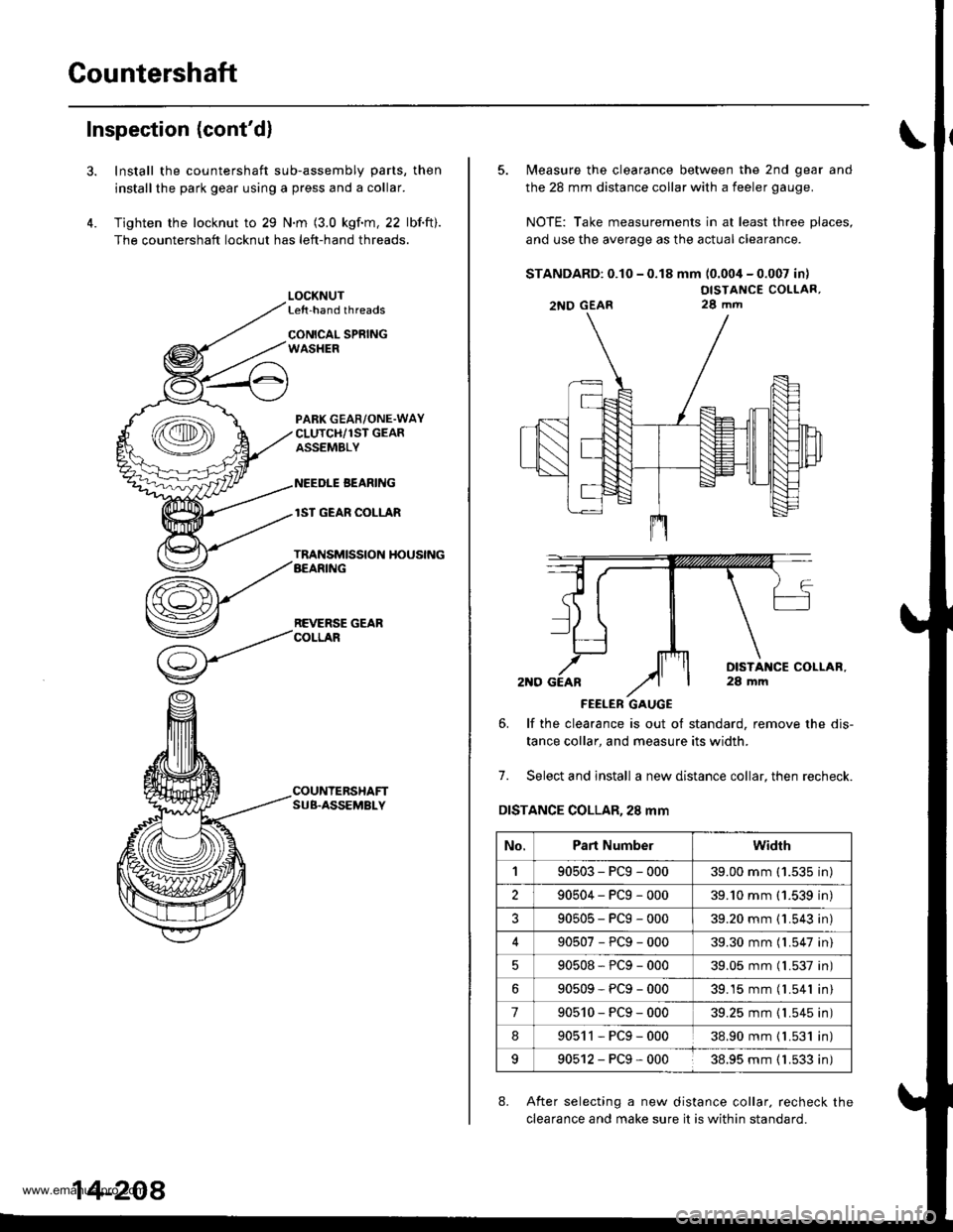
Install the countershaft sub-assembly parts, then
installthe park gear using a press and a collar.
Tighten the locknut to 29 N.m (3.0 kgf.m, 22 lbf.ft).
The countershaft locknut has left-hand threads.
LOCKNUTLe{t-hand threads
CONICAL SPRINGWASHER
PABK GEAR/ONE.WAYCLUTCH/1ST GEARASSEMBLY
NEEDLE BEANING
lST GEAR COLLAR
TRANSMISSION HOUSINGAEARING
REVERSE GEARCOLLAR
COUNTERSHAFTSUB.ASSEMBLY
14-208
5. Measure the clearance between the 2nd gear and
the 28 mm distance collar with a feeler gauge.
NOTE: Take measurements in at least three places,
and use the average as the actual clearance.
STANDARD: 0.10 - 0.18 mm (0.004 - 0.007 in)
OISTANCE COLLAR,28 mm
FEELER GAUGE
6. lf the clearance is out ot standard, remove the dis-
tance collar, and measure its width.
7. Select and install a new distance collar, then recheck.
DISTANCE COLLAR,28 mm
8. After selecting a new distance collar. recheck the
clearance and make sure it is within standard.
2NO GEAR
No.Part Numberwidrh
190503-PCg-00039.00 mm ('1.535 in)
290504-PCg-00039.'10 mm (1.539 in)
?90505-PCg-00039.20 mm {1.543 in)
90507-PCg-00039.30 mm (l.547 in)
90508*PCg-00039.05 mm (l.537 in)
90509-PCg-00039.15 mm (l.541 in)
790510-PCg-00039.25 mm {1.545 in)
890511-PCg-00038.90 mm { L531 in)
990512-PCg-00038.95 mm ( 1.533 in)
www.emanualpro.com
Page 742 of 1395
Differential
Side Clearance Inspection
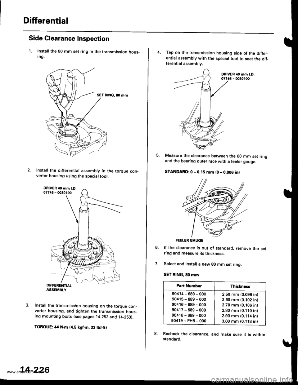
1. Instsll the 80 mm set ring in the transmission hous-Ing,
SET RING, 80 mrn
Install the differential assembly in the torque con-verter housing using the specialtool.
Install the transmission housing on the torque con-verter housing, and tighten the transmission hous-ing mounting bolts (see pages 14-252 and t4-253).
TOROUE: 4a N.m l/r.5 kgf.m, 33 tbt.ftl
14-226
4. Tap on the transmission housing side of the diffsrential assembly with the special tool to seat the dif-ferential assemblv.
DBIVER ilo m.n LO.0t746 - 0030100
Measure the clearancs between the 80 mm set ringand the bearing outer race with a feeler gauge,
STANDARD: 0 - 0.15 mm (0 - 0.006 inl
FEEI..ER GAUGE
lf the clearance is out of standard, remove rne setring and measurs its thickness.
Select and instsll a new 80 mm set ring.
SET RING, 80 mm
Recheck the clearance, and make sure it is withinstandard.
7.
Part NumborThicknoss
90414-689-000
90415-689-000
90416-689-000
90417-689-000
90418-689-000
90419-PH8-000
2.50 mm (0.098 in)
2.60 mm (0.102 in)
2.70 mm (0.106 inl
2.80 mm (0.110 in)
2.90 mm (0.114 in)
3.00 mm (0. t'18 inl
www.emanualpro.com
Page 787 of 1395
Detent Spring Replacement
1.Install the detent spring on th€ shift lever control
bracket, and installthe screw loosely.
Shift the shift lever to E position.
lnssrt a 0.5 mm (0.02 in) wire gap gauge between
the control chocker detent and the shift lever, then
hold the shift lever against the El position in the
control checker.
SHIFI LEVER
GAP GAUGE
4. Put the detent spring roller in E position on the
detent guide, then tighten the screw to the specified
torque,
'97 - 98 Modeb:
DETENT SPRING
2.5 N.m 10.25 kgf.m, 1.8lbl.ftl
SCREW2.5 N.m 10.25 kgl.m, 1.8lbtftl
14-271
www.emanualpro.com
Page 847 of 1395
Ret. No, I Tool NumbelDescriptionfty Page Reference
o
o
-@
€r
o
@rol
@
o
@
@(}
@
@
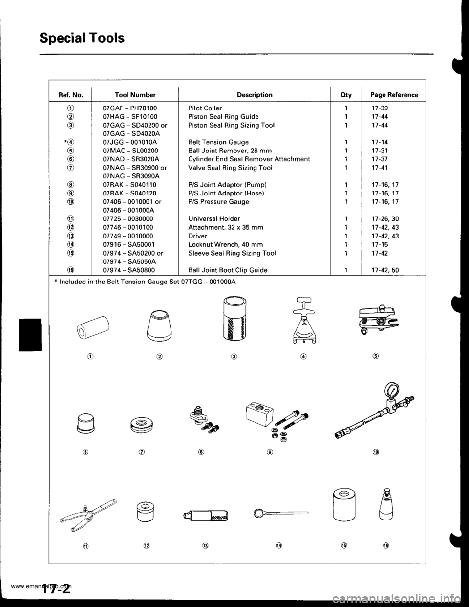
07GAF - PH70100
07HAG - SF10100
07GAG - SD40200 or
OTGAG - SD4O2OA
07JGG - 001010A
07MAC - S100200
OTNAD _ SR3O2OA
07NAG SR30900 or
07NAG , SR3OgOA
07RAK - 50401 10
07RAK - 5040120
07406 - 0010001 or
07406 - 0010004
07725 - 0030000
07746 - 0010100
07749 - 0010000
07916 - SA50001
07974 - SA50200 or
07974 - SA5050A
07974 - SA50800
Pilot Collar
Piston Seal Ring Guide
Piston Seal Ring Sizing Tool
Belt Tension Gauge
Ball Joint Remover,23 mm
Cylinder End Seal Remover Attachment
Valve Seal Ring Sizing Tool
P/S Joint Adaptor (Pump)
P/S Joint Adaptor (Hose)
P/S Pressure Gauge
Universal Holder
Attachment, 32 x 35 mm
Driver
Locknut Wrench, 40 mm
Sleeve Seal Ring Sizing Tool
Ball Joint Boot Clip Guide
'l
1
1
1
1
1
1
1
1
1
1
1
1,l
1
1
11-39
17-44
11-44
17 -14't]-31
17 -37't7 -4'l
17-'t6, 17
17-16, 17
11-16, 17
17-26,30't]-42, 43't1-42, 43
11-15't]-42
11-42, 50
* Included in the Belt Tension Gauge Set 07TGG - 001000,4
o@
\J
,/:\
I
o
,€l-
=tt
@@
aA)
l:I/\L----.--.--------_
@o(D(9@@
17-2
www.emanualpro.com
Page 852 of 1395

Uneven or rough steering.Ad,ust the rack gu ide (see page 17- 15).
ll the problem is not corrected byadjusting the rack guide, replacethe gearbox.
Adjust the belttension. Replace thebelt, if necessary (see page 17-14).Belt slipping on pulley.
lf the engine stalls when thewheel is turned while the vehicleis stopped or moving at lowspeed, adjust the idle speed (seesection 111.
ldle speed low or erratic.
Check power steering lluid level. lfthe level is excessively low checkfor leaks in the system. Add fluidto the specified level.
Air in reservoir, or check powersteering tluid level.
lf fluid level is OK, check O-ringsand seals on both ends of thepump inlet hose, and the P/Spump housing mating surlacesand drive shaft oil seal for suction leaks. Check the reservoir forcracks, Replace parts as neces-
Pump belt slipping on pulley(pump stops momentarily).Adjust the belt tension (see page17-14) or replace belt.
Check if pump pressure is normaland the gauge needle travel is 500kPa (5 kgl/cm,, 71 psi) or less.Check the flow control valve if theneedle travel exceeds 500 kPa (5kgflcm'�, 71 psi). lI the flow controlvalve is normal, replace the pumpas an assembly,
Install the power steering pres-sure gauge, Close the pressurecontrol valve and shut off valve (if
so equipped) fully and measurethe pump pressure (see page 17-16ot 17 17).
Steering wheel kicks backduring wide turns.
7-7
www.emanualpro.com
Page 859 of 1395
Inspection and Adjustment
Pump Belt
When using a new belt. first adjust the deflection or ten-
sion to the values for the new belt, then readjust the
deflection or tension to the values for the used belt after
running engine for five minutes.
Inspection
Note these items during inspection:
a lf there are cracks or any damage evident on the belt,
replace it with a new one.
. Follow the manufacturer's instructions lor the tension
gauge.
'1. Remove the P/S reservoir from the bracket, and set
it aside.
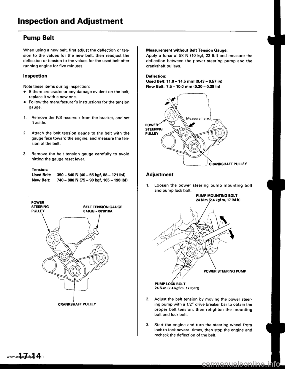
2. Attach the belt tension gauge to the belt with the
gauge face toward the engine, and measure the ten-
sion of the belt.
Remove the belt tension gauge carefully to avoid
hitting the gauge reset lever.
Tension:
Used Belt: 390 - 540 N {40 - 55 kgf, 88 - 121 lbf)
New Belt: 7,[0 - 840 N (75 - 90 kgf, 165 - 198 lbf)
CRANKSHAFT PULLEY
17-14
Measurement without Belt Tension Gauge:
Apply a force ot 98 N (10 kgf,22 lbt) and measure the
deflection between the power steering pump and the
crankshaft oullevs.
Deflection:
Used Belt: 11.0 - 1i1.5 mm {0.'(l - 0.57 in)
New Belt: 7.5 - 10.0 mm {0.30 - 0.39 in)
CRANKSHAFT PULLEY
Adiustment
'1. Loosen the power steering pump mounting bolt
and pump lock bolt.
PUMP MOUNNNG BOLT24 N'm (2.4 kgf'm, 17 lbf ftl
PUMP LOCK BOLT24 N.m 12.4 kgf.m, 17 lbf.ftl
Adjust the belt tension by moving the power steer-
ing pump with a 1/2" drive breaker bar to obtain theproper belt tension, then retighten the mounting
bolt and lock bolt.
Start the engine and turn the steering wheel from
lock-to-lock several times, then stop the engine and
recheck the deflection of the belt.
Measure here.
www.emanualpro.com
Page 861 of 1395
lnspection and Adjustment
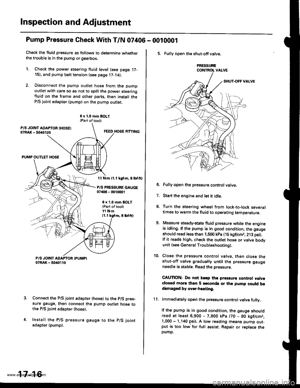
Pump Pressure Gheck With T/N 07406 - 0010001
Check the fluid pressure as follows to determine whetherthe trouble is in the pump orgearbox.
1. Check the powsr steering fluid level (see page 17-15), and pump belt tension (see page 17-14).
2. Disconnect the pump outlet hose from the pump
outlet with care so as not to spill the pow€r steeringiluid on the frame and other pans. thon install theP/S joint adapter (pumpl on the pump outlet.
6 x 1.0 mm BOLT{Part oftool)
FEED HOSE FITTING
PUMP OUTLET HOSE
11 N.m ll.1 kgl.m, E lbf.ftl
P/S PRESSURE GAUGE07('6 - 0010001
6 x t.0 mm BOLT{Part oftool)11 N.m(1.1 kgt m, 8 lbf.tr)
Connect the P/S joint adapter (hose) to the p/S pres-
sure gauge, then connect the pump outlet hose tothe P/S ioint adspter (hose).
Install the P/S pressure gauge to the p/S joint
adapter (pump),
17-16
5. Fully open the shut-off valve.
PRESSURECONTROL VALVE
6. Fully open the pressure controlvatve.
7. Start the engine and let it idle.
8. Turn the steering wheel from lock-to-lock severaltimes to warm the fluid to operating temperature.
9, Measure steady-state fluid pressure while the engineis idling. lf the pump is in good condition, the gauge
should read less than 1,500 kPa (15 kgf/cmr, 213 psi).
lf it reads high, check the outlet hose or valve bodvunit (see General Troubleshooting).
10. Close the pressure control valve, then close theshut-off valve gradually until the pressure gauge
nsedle is stable. Read the pressure.
CAUTION: Do not k€ap tha prca3un control valvoclorod mo.c thon 5 srconds or thc pump cluld bodamEgod by ovor-hoating.
11. lmmodiately open the pressure controlvalve fullv.
lf the pump is in good condition, the gauge shouldread at least 6,900 - 7,800 kpa (70 - 80 kgflcmr,'1,000 - 1.140 psi). A low reading means pump out-put is too low for full assist. Repair or replace theDUMD.
www.emanualpro.com