1999 HONDA CR-V speed sensor
[x] Cancel search: speed sensorPage 629 of 1395

Check Countershaft Speed Sen-sor for a Short Circuit:'1. Disconnect the D (16P) connector from the PCM.2. Check lor continuity betweenbody ground and the D10 ter-minal and Dl6 terminal indi-vidually.
Repair short in the wire3 botweonthe Dl0 and D16 terminals andthe countershaft 3De€d sensor.
Measure Countershatt SpeedS6n3or Circuit to. an Open:1, Co n nect the countershaftspeeo sensor connector,2. Measu re the resistancebetween the D10 and D16 ter-mrnals,
Repair loose terminal or open inthe wiies between the D10 andO16 terminals and th. countet-shaft sD€ed sensor.
ls the resistance 400 - 600 0?
Check tor loos. terminal fit in thePCM conn€ctoas. It necessary,substitute a known-good PCMand recheck.
From page 14'112
A t32PlB (25P1
a l32PlB (25P1
PCM CONNECTORS
Wire side ol female terminals
NC IBLUI
D {16P1
NCSG IGRNI
c l31P)
ial, tu]g
c (31PI
NCSG IGRN}
14-113
www.emanualpro.com
Page 630 of 1395

Electrical Troubleshooting ('98 - 00 Modelsl
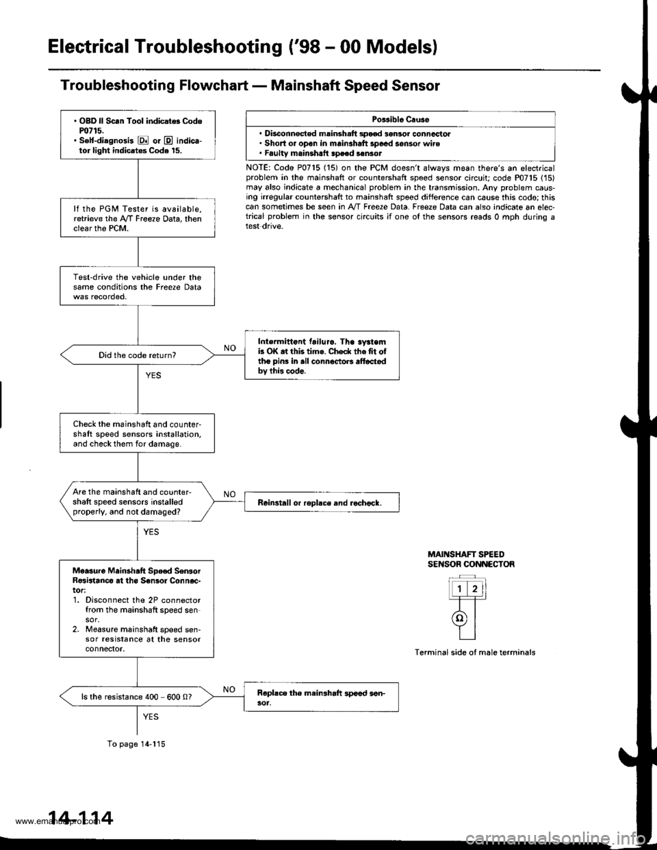
Troubleshooting Flowchart - Mainshaft Speed Sensor
Porsible Cruse
. Disconnsct€d msinsh.ft 3pood 3gnlor conncctol. Short or open in mainshaft 3poed sensor wire. Faultv mainshrtt speed sonsot
NOTE: Codo P0715 (15) on the PCM doesn't always moan there's an electricalproblem in the mainshaft or countershaft speed sensor circuit; code P07'15 (15)may also indicate a mechanical problem in the transmission. Any problem caus-ing irregular countershaft to mainshaft spoed difference can cause this codo; thiscan sometimes be seen in A'/T Free2e Data. Freeze Data can also indicate an elec-trical problem in the sensor circuits ;f one of the sensors reads 0 mph during atest dnve.
MAINSHAFT SPEEDSENSOR CONNECTOR
Terminal side of male terminals
. OBD ll Scan Tool indicat$ Codem715.. S€lf-diagnosi3 E or @ indica-tor light indicatos Code 15.
lf the PGM Tester is available,retrieve the A/f Freeze Data, thenclear the PCM.
Test-drive the vehicle under thesame conditions the Freere Data
Intermittont tailuro. Tha sy3temb OK at this tims. Check thefit oftho pins in .ll connoctoB alt6ctedbv this code.
Did the code return?
Check the mainshaft and counter-shaft speed sensors installation,and check them for damage.
Are the mainshaft and counter-shaft speed sensors installedproperly, and not damaged?Reinstall or ropllce and rochock.
Moasure Mainshatt Spe€d SenrorR€sirtanco at ths S€nsol Connoc-tor:1. Disconnect the 2P connectorfrom the mainshaft speed sensor.2. Measure mainshatt speed sen-sor resrstance at the sensorconnefior.
ls the resistance 400 600 0?
To page 14-115
14-114
www.emanualpro.com
Page 631 of 1395

A {32P}
From page 14-114
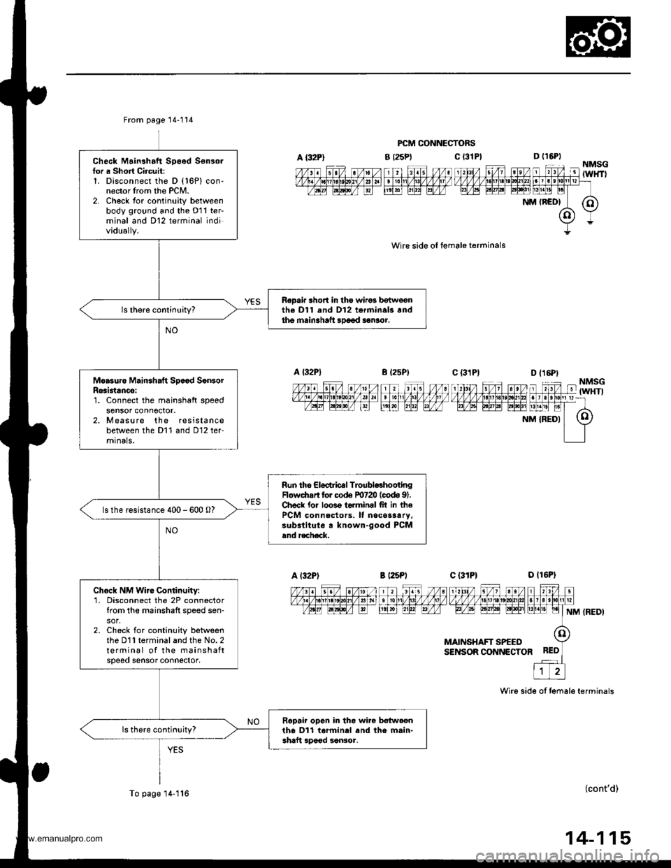
Check Mainshaft Speed Sensorfor a Short Circuit:1. Disconnect the D (16P) con-nector trom the PCM.2- Ch€ck tor continuity betweenbody ground and the D11 ter-minal and Dl2 terminal individually.
ReDair short in tho wiros botwe€nth€ Dl1 and D12 torminal3.ndtho main3haft 3Doed aonlor.
Moasure Mainshaft Sp6€d SonsorRosi3tancei1. Connect the mainshaft speedsensor conn6ctor.2. Measure the resistancebetween the Dl1 and D12 ter-mrnals,
Run the Eloctric€l TroubldhootingFlowdrrrt for co& F0720 (codo 91.Chock lor loo3o torminrl fit in thePCM connectors. It necos3ary,substitute r known-good PCMand r€ch€ck.
ls the resistance 400 - 600 0?
Chock NM Wire Continuity:1. Disconnect the 2P connectortrom the m6inshaft speed sen-
2. Check for continuity betweenthe D11 terminal and the No. 2terminal of the mainshaftspeeo sensor connector,
Rcpair opon in tho wire betw.enth6 Dll tarminal and the main-shaft lpood sonsor.
To page'14-1'16
PCM CONNECTORS
c t3lPl
wire side ol female terminals
B l25Pt
D t16PtNMSG-'lTZ lit4'l Fl l'1til FTil ,'l unrv v v v v l.t1lLtLt?!/]|,1tut larrlrllllpr=rtavtq tptntat EElt [1!]t! pl
NM (RCD| (O)
(o)Y
Y=
c {31P1--_|--1\‰1,/ s/1 st/v,1zzfififinffiiFrF/l,6t FFF| LrLrEllNM {REDI
MAINSHAFT SPEEOSENSOR CONNECTOR
Wire side of temale terminals
(cont'd)
14-115
www.emanualpro.com
Page 632 of 1395

Electrical Troubleshooting ('98 - 00 Models)
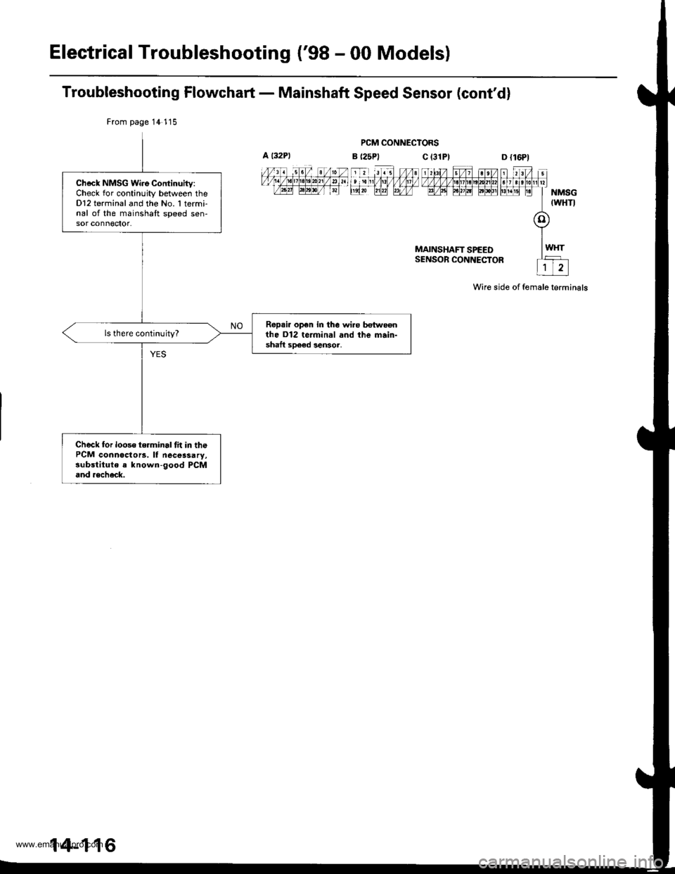
Troubleshooting Flowchart - Mainshaft Speed Sensor (cont'd)
PCM CONNECTORS
MAINSHAFT SPEEDSENSOR CONNECTOR
Wire side of female terminals
From page 14 115
Ch6ck NMSG Wire Continuitv:Chock for continuity between theDl2 terminal and the No. 1 termi-nal of the mainshaft speed sen-sor conn€ctot.
Ropai. op€n in the wi.e hn eonthe D12 terminal and the main-shaft sDeed lensor,
ls there continuity?
Check for looso terminal fit in thePCM connoctorc. lf necessary,substitute a known-good PCMand aech6ck.
14-116
www.emanualpro.com
Page 654 of 1395

Mai nshaft /Cou ntershaft
Linear Solenoid AssemblySpeed Sensors
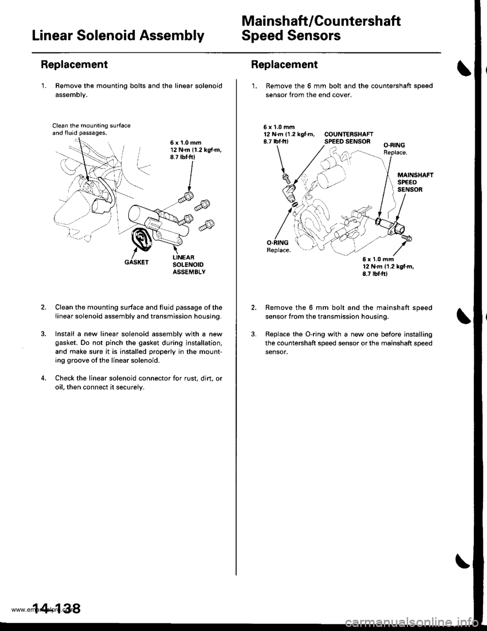
Replacement
'1. Remove the mounting bolts and the linear solenoid
assemblY.
Clean the mounting surfaceand fluid passages.
6x1.0mm12 N.m (1.2 kg{.m.8.7 tbtftl
@
@
GASKET
Clean the mounting surface and fluid passage of the
linear solenoid assembly and transmission housing.
Install a new linear solenoid assemblv with a new
gasket. Do not pinch the gasket during installation,
and make sure it is installed properly in the mount-
ing groove of the linear solenoid.
Check the linear solenoid connector for rust. dirt, or
oil, then connect it securelv.
14-138
Replacement
1. Remove the 6 mm bolt and the countershaft sDeed
sensor from the end cover.
\
5x1.0mm12 N.m 11.2 kgf.m, COUNTERSHAFT8.7 rbf.frl SPEED SENSOR
O.RINGReplace.
12 N'm 11.2 kgl.m,8.7 tbf.ftl
Remove the 6 mm bolt and the mainshaft speed
sensor from the transmission housing.
Replace the O-ring with a new one before installing
the countershaft speed sensor or the mainshaft speed
sensor,
6x1.0mm
www.emanualpro.com
Page 670 of 1395

Symptom-to-Component Chart
Hydraulic System (cont'd)
SYMPTOMCheck these items on thePROBABLE CAUSE ListCheck these items onthe NOTES Lisr
Shift lever does not operate smoothly.o, JdPFails to shift; stuck in 4th gear.14, 41 , 48
Transmission will not shift into park in E position.6, 38, 61PStall rpm high; all clutch pressures are in specification.40D,K,OLock-up clutch does not disengage.18, 43, 44, 45, 46, 49,50,57
Lock-up clutch does not operate smoothly.14, 40, 43, 44, 45, 46, 49, 50. 57Lock-up clutch does not engage.'t8, 40, 43, 44, 45, 46, 49, 50, 56, 57Vibration in all positions.
No engine braking in I position.59
Shift position indicator does not indicate anv position,6. 38, 60
PROBABLE CAUSE
I 33 Thrust washer worn/damaged
ATF pump worn or binding34Clutch clearance incorrect
Regulator valve stuck or regulator valvespflng wornDrive plate delective or transmission mtsas-sembled
Servo valve stuck5ttTorque converter housing or transmissionhousing bearing worn/damagedMainshaft worn/damaged
Shift cable broken/out of adjustmentATF strainer clogged
7Final gears worn/damaged38Shift cable is worn where it attaches to thetransmission or at the body mountsIOne-way (sprag) clutch worn/damaged
1st gears worn/damaged {2 gears)39Modulator valve stuck10lst clutch defective40Torque converter check valve stuck112nd gears worn/damaged (2 gears)41Foreign material in separator plate't22nd clutch defectiveCPB valve stuck
t53rd clutch defective43Lock-up timing valve stuck144th clutch defective44Lock-up shift valve stucktcReverse gears worn/damaged (3 gears)Lock-up control valve stuck16Excessive ATF46Lock-up clutch Diston defective17Torque converter one-way clutch defective47Shift control solenoid valve A defecttve
18Linear solenoid assemblv defective (,98 - OOmodels)48Shift control solenoid valve B dsfectrve
49Lock-up control solenoid valve A defective'19CPC valve stuckLock-up control solenoid valve B deleqtve20l-2 shift valve stuck51Servo control valve stuck212-3 shift valve stuck52lst accumulator defective3-4 shift valve stuck53Foreign material in 2nd exhaust orifice2nd accumulator defective54Foreign material in 3rd exhaust orifice3rd accumulator defectiveForeign material in 4th exhaust orifice4th accumulator defective56Mainshaft speed sensor defective262nd orifice control valve stuckCountershaft speed sensor defective273-4 orifice control valve stuck583rd sub accumulator defective2aForeign material in main orifice59lst-hold clutch defective29Foreign material in lst orifice60A/T gear position switch defective or out ofadjustment30Foreign material in reverse orifice
31Engine output low61Park gear mechanism defective32Needle bearing worn/damaged
14-154
www.emanualpro.com
Page 673 of 1395

Road Test
NOTE: Warm up the engine to normal operating temperature (the radiator tan comes on).
1. Before testing, check the transmission fluid level, see page 14-160.
2. Apply the parking brake and block the wheels. start the engine, then shift to E {'97 - 98) or E {'gg - 00) position
while pressing the brake pedal. Press the accelerator pedal and release it suddenly. The engine should not stall.
3. Repeat same test in E position ('97 - 98 models).
4. Test-drive the vehicle on a flat road in the E or E position. Check that the shift points occur at approximate speeds
shown on a flat road. Also check for abnormal noise and clutch slippage.
Throttle position sensor voltage represents the throttle opening. Monitor it with the Honda PGM Tester or as follows:
a. Unbolt the PCM for road testing; reJer to page 14-58.
b. Set the digital multimeter to check throttle position sensor voltage between these terminals on the PCM:
. '97 Model: Between terminals D'! (+) and A9 (-) or A22 {-}
. '98 - OO Models; Between terminals C27 (+) and 820 (-) or 822 {-)
BACKPROBE ADAPTER
BACKPROBE SETorsAz - 001moA(two roquircdl
STACKING PATCH
CORD
DIGiTAL MULTIMETER
{Comm€rcirllY .vailablc}KS-AHM-32-003,or equival.nt
'97 Model:PCM CONNECTORS
'98 - 0O Models:
A l32Pt
Wire side of female terminals
PCM CONNECTORS
B {25Pt c l31P}
(cont'd)
LGl (BRN/BLK)
'. //B 1 l'o ti , jl. to a 2r / / 11111t1.t nait la t1 t213tr / t6t, tl / / / / 1 3 / 10n v
t-'a:IM-&E -Llfiffi-fl)\"".'E
Wire side ot female termanals14-157
www.emanualpro.com
Page 674 of 1395

Road Test
(cont'd)
lgrr or E Position:
Upshift
NOTE:
. Lock-upON:The lock-up control solenoid valve A turns ON.. Lock-up OFF: The lock-up control solenoid valve A turns OFF.
4. Accelerate to about 35 mph (57 km/h) so the transmission is in 4th. then shift from E or E position to E position.The vehicle should immediately begin slowing down from engine braking.
5. Check for abnormal noise and clutch slippage in the following positions.
E {1st Gear) Position
Accelerate from a stop at full throttle, Make sure there is no abnormal noise or clutch slippage.Upshifts should not occur with the shift lever in this position.
E (2nd cear) Position
Accelerate from a stop at fuI throttre. Make sure there is no abnormar noise or crutch srippage.Upshifts and downshifts should not occur with the shift lever in this position.
E (Reverse) Position
Accelerate from a stop at full throttle. and check for abnormal noise and clutch slippage.
6. Test in E (Park) Position
Park the vehicle on slope (approx. 16"), apply the parking brake, and shift into E position. Release the brake; the vehi-cle should not move.
Throftle OpsningUnit of sps€dlsi + 2nd2nd * 3rd3rd + ilthLock-up ON
Throttle position sensor
voltage: 0.75 V
mph9-1220-2328-33
km/h15-1945-5334-40
Throttle position sensor
voltage; 2.25 V
mph22-2643-49oz - ott68-74
km/h35-4169-7999 - 108109 - 118
Fully-opened throttle,
Throttle position sensor
voltage: 4.5 V
mph37-43101 - 11190 - 101
k-/h60-69111 - 124163 - 179145 - 163
Downshift
Throttle OpeningUnit ot speedLock-up OFFi{th + 3rd3rd * 2ndznd + lst
Fully-closed throttle,
Throttle position sensor
voltage; 0.5 V
mpn19-231A - 2'l6 - 10 {3rd - 1st)
km/h5t-5D29-3410 - 15 (3rd * 1st)
Fully-opened throttle,
Throttle position sensor
voltage: 4,5 V
mph88-9986-9657 -6426-32
km/h142 - 't59138 - 15492 - 10342-51
14-158
www.emanualpro.com