Page 821 of 1395
Front Driveshafts
Disassembly (cont'd)
Double Loop
Mark each roller and inboard joint to identify the
locations of the rollers and grooves in the inboardjoint. Thon remove the inboard ioint on the shop
towel. Be careful not to drop the rollers when sepa-
rating them from the inboard joint.
INBOARD JOINTCheck splines for wear or damage.Check inside bore for wear.Inspect for cracks.
16-6
4, Mark the rollers and spider to identify the locstions
of the rollers on the sDider, then remove the rollers.
BEARING REMOVER(Commercially available) DRIVESHAFT
Remove the circlip,
Mark the spider and driveshaft to identify the posi-
tion ofthe spider on the shaft.
Remove the spider using a bearing remover,
Wrap the splines on the driveshaft with vinyl tape to
prevent damage to the boots and dynsmic damper,
7.
q
INBOARD BOOT
DRIVESHAFT
DYNAMIC DAMPER
Rsmove the inboard boot and dvnamic
Take care not to damage the boot and
damDer.
damper.
dynamic
DRIVESHAFT
Mark
www.emanualpro.com
Page 825 of 1395
Front Driveshafts
Reassembly {cont'd)
7. Fit the inboard joint onto the driveshaft, and note
these items:
Reinstall the inboard joint onto the driveshaft by
aligning ths marks on the inboard joint with the
marks on the rollers.
Hold the driveshaft so the inboard joint points up
to prevent it from falling off.
Adjust the length of the driveshafts to the specifica-
tions shown. then adjust the boots to halfway
between full compression and full e)dension. Make
sure the ends of the boots seat in the grooves of the
driveshaft and Ioint.
/€\
/,?:..�{ \
t Sptine airection
lffi
tYl:\
ROLLER HOLDER
16-10
Left: 508 - 513 mm 120 - 2O.2 inl
Right: AT model 520 - 525 mm {20.5 - 20.7 in)
MT mod6l 515 - 520 mm (20.3 - 20.5 inl
II
-flm+dm@
9. Position the dynamic damper to the specifications
as snown.
Left: 299.5 t 2 mm 111.8 r O.l inl
Right: 299.5 t 2 mm 111.810.1 inl
OUTBOARO JOINT
www.emanualpro.com
Page 826 of 1395
10. Set the double loop band onto the boot or dynamic
damper with the band end toward the front of the
vehicle.
11. Pull up the slack in the band by hand.
12. Make a mark on the band 10 - 14 mm (0.4 - 0.6 in)
from the clip.
OOUBLE LOOP BAND
CLIP
13.
'14.
Thread the free end of the band through the nose
section of a commercially available boot band tool(KD-3191 or equivalent). and into the slot on the
winding mandrel.
Place a wrench on the winding mandrel of the boot
band tool. and tighten the band until the marked
spot on the band meets the edge of the clip.
BOOT BAND TOOL(KD-3191
or equivalentlMark on band.
15.
WINDINGMANDREL
Lift up the boot band tool to bend the free end of
the band 90 degrees to the clip, Center-punch the
clip, then fold over the remaining tail onto the clip.
(cont'd)
16-1 1
HAMMER
www.emanualpro.com
Page 830 of 1395
13. Fit the boot ends onto the driveshaft and the out-
board joint.
14. Fit the double looD boot bands onto the boot ends
15.
16.
Pull up the slack in the band by hand.
Mark a position on the band 10 - 14 mm (0.4 - 0.6
in.) from the clip.
Thread the free end of the band through the nose
section of a commercially available boot band tool
(KD-3191 or equivalentl, and into the slot on the
winding mandrel.
17.
BOOT BAND TOOL(Commercially available)KD-3191 or equivalentMark spot.
(cont'd)
16-15
CLIP
www.emanualpro.com
Page 833 of 1395

Front DriveshaftsIntermediate Shaft
Installation {cont'd}
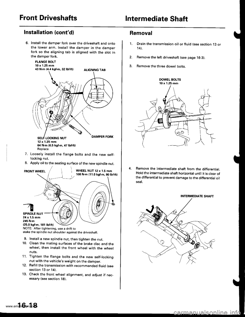
Install the damper fork over the driveshaft and ontothe lower arm. Install the damper in the damperfork so the aligning tab is aligned with the slot inthe damper fork.
FLANGE BOLT10 x 1.25 mm€ N.m {4.i1kst.n,32 lbf.ftl ALtcNtNG TAB
12x 1.25 mm64 N.m {6.5 kgf.m, 47 lbf.ftlReplace.
7. Loosely install the flange bolts and the new self-locking nut.
8. Apply oil to the seating surface of the new spindle nut.
FRONT WHEELi WHEEL NUT 12 x 1.5 mm108 N.m (11.0 kgf.m,80lbf.ftl
SPINDLE NUT24 x 1.5 mm245 N.m{25.0 ksf.m, 181 lbf.ft)NOTE: Atter tightening. use a drift tostake the spindle nut shoulder against the driveshaft.
9. Install a new spindle nut, then tighten the nut.10. Clean the mating surfaces of the brake disc and thewheel. then install the front wheel with the wheelnuts,
1'1. Tighten the flange bolts and the new setf-lockingnut with the vehicle's weight on the damper.12. Refill the transmission with recommended fluid (see
section 13 or 14).
13. Check the front wheel alignment. and adjust if nec-essary (see section 18).
16-18
1.
Removal
Drain the transmission oil or fluid (see section 13 or14).
Remove the left driveshaft (see page 16-3).
Remove the three dowel bolts.
Remove the intermediate shaft from the differential.Hold the intermediate shaft horizontal until it is clear ofthe differentialto prevent damage to the differential oilseal.
INTERMEDIATE SHAFT
www.emanualpro.com
Page 837 of 1395

Rear Driveshafts
't.
Removal
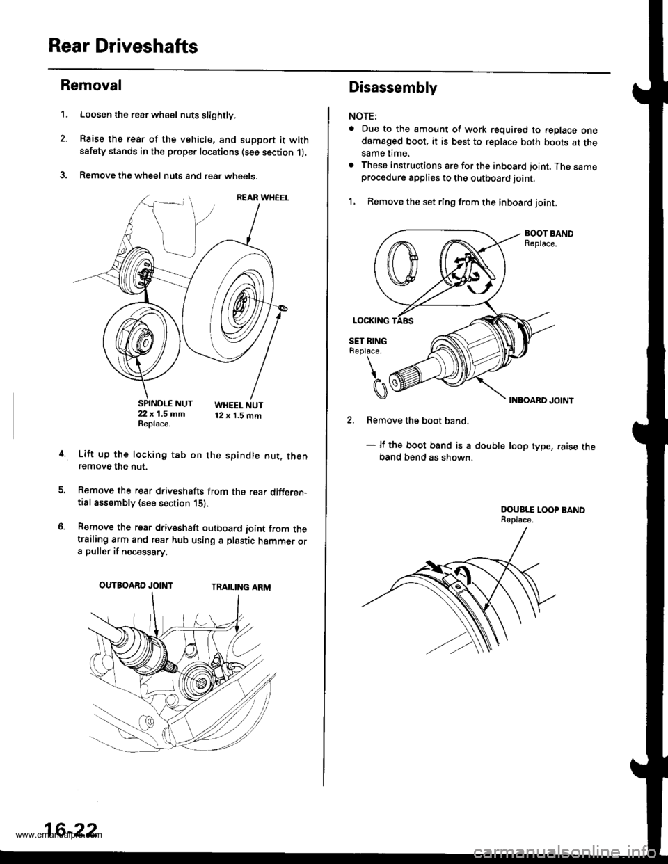
Loosen the rear wh€el nuts slightly.
Raise the rear of the vehicle, and support it withsafety stands in the proper locations (see section 1),
Remove the wheel nuts and rear wheets.
SPINDLE NUT22 x 1.5 mmReplace.
WHEEL NUT12 x 1.5 mm
4.Lift up the locking tab on the spindle nut. thenremove the nut.
Remove the rear driveshafts from the rear differen-tial assembly (see section 15),
Remove the rear driveshaft outboard joint from thetrailing arm and rear hub using a plastic hammer ora puller if necessary.
TRAILING ARMOUTBOARD JOINT
16-22
Disassembly
NOTE:
a Due to the amount of work required to replace onedamaged boot, it is best to replace both boots at thesame time.
. These instructions are for the inboard joint. The sameprocedure applies to the outboard joint.
1, Remove the set ring from the inboard joint,
BOOT BANDReplace.
INBOARD JOINT
2. Remove the boot band.
- lf the boot band is a double loop type, raise theband bend as shown,
DOUSLE LOOP BANDReplace.
www.emanualpro.com
Page 838 of 1395
3. Mark each roller and inboard joint to identify the
locations of rollers and grooves in the inboard joint.
Then remove the inboard joint on the shop towel.
INBOARD JOINTCheck splines and driveshaft ringfor wear or damage,Check inside bore for wear.Inspect {or cracks,DRIVESHAFT RING
M.rks
SHOP TOWEL
Mark the rollers and spider to identify the locations
of the rollers on the sgider, then remove the rollers,
ROLLER
Remove the circlip.
Mark the spider and driveshaft to identify the posi-
tion of the spider on the shaft.
Remove the spider using a bearing remover.
0\
t
ICIRCLIP
Mark
7.
Marks
DRIVESHAFT
INEOARD BOOTInspect for cracking,splitting and wear.
10.
'1 1.
8. Wrap the splines on the driveshaft with vinyl tapeto
prevent damage to the boots.
DRIVE
Remove the boot band and boot from the drive-
shaft. Take care not to damage the boot.
Remove the vinyl tape.
Inspect the driveshaft for damage and other faults.
16-23
www.emanualpro.com
Page 840 of 1395
'1. Wrap the splines with vinyl tape to prevent damage
to the boots.
lnstall the boots onto the driveshaft, and seat the
small end of the boots into the grooves on the drive-
shaft, lf the small ends of the boots are not seated in
the grooves, the boot length adiustment will be
rncorrect.
Remove the vinyl tape from the end of the driveshaft.
Install the spider onto the driveshaft by aligning the
mark on the spider with the mark on the end of the
driveshaft.
lnstall a new circlip into the end g.oove on the drive-
shaft. Rotate the circlip in its groove to make sure its
fullv seated.
VINYL TAPE
6. Reinstall the rollers to their original positions on the
spider by aligning the marks. After installation, make
sure to hold the driveshaft pointed straight up to pre-
vent the rollers from falling off.
Pack the joint and the boot with the joint grease
included with the new boot.
Grease quantity: 80 - 90 s {2.8 - 3.2 o2)
7.
ROLLER
(cont'd)
16-25
www.emanualpro.com